| Author |
Message |
elektrouwe
Joined: May 27, 2012
Posts: 146
Location: Germany
|
|
|
Back to top
|
|
 |
steffensen

Joined: Jul 11, 2012
Posts: 103
Location: Sweden
|
 Posted: Sun Mar 31, 2013 2:30 am Post subject: Posted: Sun Mar 31, 2013 2:30 am Post subject:
|
  |
|
| I have nothing to add here, only that im glad someone finally picked this up. Will follow with interest! |
|
|
Back to top
|
|
|
keyman2
Joined: Jul 16, 2013
Posts: 6
Location: Canada
|
| Posted: Sat Jul 27, 2013 10:39 pm Post subject:
Re: CS-80 style VCO |
|
|
Looks deceptively simple...What would be required to make this a 'practical circuit' in terms of compensation for temperature or other variations which might alter tuning/performance?
| elektrouwe wrote: | here is a schematic for a CS-80 style VCO. It is only a LTSPICE simulation until now. A guy asked for help on a german forum ( http://www.sequencer.de/synthesizer/viewtopic.php?f=13&t=78218 ) and I found it interesting to help him, because Yamaha used a closed loop VCO in their Chip. Although closed loop VCOs typically have better linearity than our "bread & butter discharge cap. with switch"-VCOs they are not popular in music electronics, because the rising ramp has a slope with fixed rise time and the amplitude is not constant over CV-range.
Rise time at low freq. does not play a role, but for frequencies in the kHz range , waveform changes towards an asymmetrical triangle. I guess that is the reason why Yamaha added a waveform shaper that simply masks the rising slope with a constant amplitude "punch" from the closed loop one-shot.
the short (30us ?) punch does not add audible harmonic content and, I guess again, is "grinded" away in the (bandwidth limited) signal path.
Please comment |
|
|
|
Back to top
|
|
|
itist

Joined: Dec 30, 2013
Posts: 16
Location: Germany
|
|
|
Back to top
|
|
|
keyman2
Joined: Jul 16, 2013
Posts: 6
Location: Canada
|
| Posted: Mon Dec 30, 2013 4:53 pm Post subject:
Re: Soundclip |
|
|
The ladder example sounds very saturated?
|
|
|
Back to top
|
|
|
itist
Joined: Dec 30, 2013
Posts: 16
Location: Germany
|
|
|
Back to top
|
|
|
itist
Joined: Dec 30, 2013
Posts: 16
Location: Germany
|
| Posted: Tue Dec 31, 2013 8:38 am Post subject:
made some new Measurements |
|
|
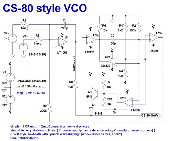
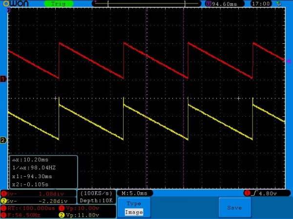
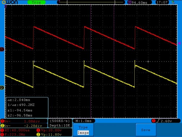
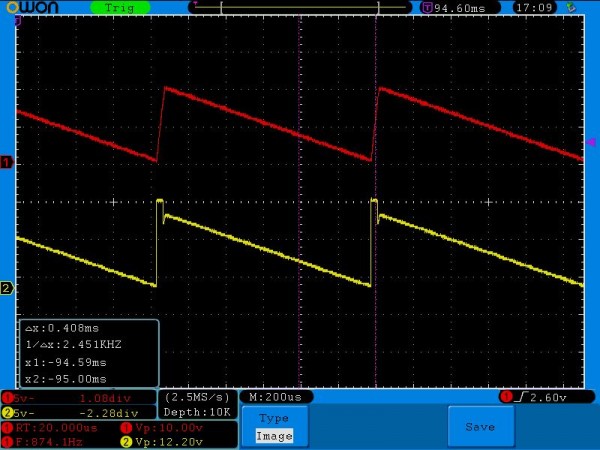
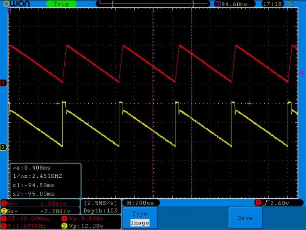
Hi,
i think one of Videos is not the CS Style VCO.
Today i have made some new measurements above the range of
125mV to 8 V in octave steps.
The voltage source is not my DAC to eliminate errors in the Voltage steps.
Voltage Frequency red Frequency yellow
0.125V 56.5Hz 56Hz
0.250V 112.5Hz 112Hz
0.5V 223.2Hz 223Hz
1V 439.9Hz 443Hz
2V 874.1Hz 874Hz
4V 1696Hz 1701Hz
8V 3226Hz 3231Hz
Measured with the Oscilloscop!!
all above 3v sounds detuned.
See Update!!
The circuit was powered wirh an standard linear Power supply no Lab supply.
Greetz
Oliver
| Description: |
|
| Filesize: |
86.38 KB |
| Viewed: |
376 Time(s) |
| This image has been reduced to fit the page. Click on it to enlarge. |
|
| Description: |
|
| Filesize: |
85.15 KB |
| Viewed: |
384 Time(s) |
| This image has been reduced to fit the page. Click on it to enlarge. |
|
| Description: |
|
| Filesize: |
84.79 KB |
| Viewed: |
369 Time(s) |
| This image has been reduced to fit the page. Click on it to enlarge. |
|
| Description: |
|
| Filesize: |
84.25 KB |
| Viewed: |
369 Time(s) |
| This image has been reduced to fit the page. Click on it to enlarge. |
|
| Description: |
|
| Filesize: |
87.96 KB |
| Viewed: |
459 Time(s) |
| This image has been reduced to fit the page. Click on it to enlarge. |
|
_________________
http://www.itist.de
https://plus.google.com/+ItistDe
http://www.youtube.com/user/DerITist
https://www.facebook.com/deriTist |
|
|
Back to top
|
|
|
itist
Joined: Dec 30, 2013
Posts: 16
Location: Germany
|
| Posted: Wed Jan 08, 2014 1:24 pm Post subject:
OpAmp changed!! |
|
|
After Uwe, the developer of the VCO, wrote me an e-mail where he asked me about the used OpAmp, i wrote him that i used an OP07 (bipolar), he told me to use jfet type. So I changed it to a LF356.
Here the results:
CV F
0.125V 49.8Hz
0.250V 99.01Hz
0.5V 197.4Hz
1V 393.8Hz
2V 784.9Hz
4V 1520Hz
8V 3140Hz
I think this is very linear.
I did a simple temperature check (hair dryer)
15C° 1000Hz
20C° 999Hz
30C° 993Hz
40C° 984Hz
46C° 977Hz
The circuit was build with standard metalfilm resitors with +- 50 ppm
Thank you Uwe.
_________________
http://www.itist.de
https://plus.google.com/+ItistDe
http://www.youtube.com/user/DerITist
https://www.facebook.com/deriTist |
|
|
Back to top
|
|
|
itist
Joined: Dec 30, 2013
Posts: 16
Location: Germany
|
|
|
Back to top
|
|
|
Yipdeceiver
Joined: Apr 07, 2014
Posts: 4
Location: Athens GA
|
| Posted: Wed Apr 23, 2014 7:54 am Post subject:
|
|
|
| I would love to make a +/- 12v version of this for my modular. What would I have to change to run this on +/-12v? |
|
|
Back to top
|
|
|
elektrouwe
Joined: May 27, 2012
Posts: 146
Location: Germany
|
| Posted: Wed Apr 23, 2014 1:49 pm Post subject:
|
|
|
[quote="Yipdeceiver"What would I have to change to run this on +/-12v?[/quote]
It will run @+-12V without problems, but a V/Hz slope change (mostly) from Iref = -V/R9 will happen.
R9 can be changed to a 12/15 lower value to get (almost) the same V/Hz slope as with +-15V.
It might be a good idea anyway to add a trimpot in series to R9 to compensate for other component tolerances. |
|
|
Back to top
|
|
|
itist
Joined: Dec 30, 2013
Posts: 16
Location: Germany
|
|
|
Back to top
|
|
|
elektrouwe
Joined: May 27, 2012
Posts: 146
Location: Germany
|
| Posted: Wed Jun 25, 2014 1:00 am Post subject:
Re: Built dual VCO Boards |
|
|
| itist wrote: | Hi,
And a first Impressions Sound Demo
|
thanks for the proof of concept , Oliver ! |
|
|
Back to top
|
|
|
steffensen
Joined: Jul 11, 2012
Posts: 103
Location: Sweden
|
| Posted: Thu Jun 26, 2014 2:56 am Post subject:
|
|
|
itist,
Would you care to share more info/details about the sync-isse you had and solved by using a buffer?
Never seen a solution like that before, only seen it solved by using precision voltage reference's and such. This makes me curious! |
|
|
Back to top
|
|
|
itist
Joined: Dec 30, 2013
Posts: 16
Location: Germany
|
| Posted: Thu Jun 26, 2014 7:05 am Post subject:
My explanation for the Sync issue. |
|
|
In my first Impression Video I connected all outputs on the Diode D1 via a summing resistor Network
to an Opamp and then to the soundcard.
My assumption is that the outputs interfere with the trigger circuit (current return path??) and with the unity gain buffer this path is cut off.
Maybe it was only a kind of capacitive coupling. But with the buffer the sync issue has gone.
The circuit ist powered with a standard linear Voltage power supply but the control voltage is created with an LT1236.
For a linear VCO you need, especially in the lower key range, a precise Voltage. The lowest C is 125mV and the next C is 250mV
so each halftone is appr. 10 mV
I will do further testing but in my first tests the VCO seems to be linear over the Voltage Range from 125mV to 4mV.
You can follow the further development on my website:
www.itist.de
And please don't forget I am not an EE!
So my answers are maybe not correct! 
Greetz
Oliver
_________________
http://www.itist.de
https://plus.google.com/+ItistDe
http://www.youtube.com/user/DerITist
https://www.facebook.com/deriTist |
|
|
Back to top
|
|
|
itist
Joined: Dec 30, 2013
Posts: 16
Location: Germany
|
| Posted: Thu Jun 26, 2014 12:09 pm Post subject:
|
|
|
| steffensen wrote: | itist,
Would you care to share more info/details about the sync-isse you had and solved by using a buffer?
Never seen a solution like that before, only seen it solved by using precision voltage reference's and such. This makes me curious! |
i will try to reproduce this issue and will do Audio and Scope Recording.
Maybe its synced because of the Scope probes?
It's also necessary to check the second board. On this board one VCO sounds muffled. THe other three sounds crisp.
Greetz
Oliver
_________________
http://www.itist.de
https://plus.google.com/+ItistDe
http://www.youtube.com/user/DerITist
https://www.facebook.com/deriTist |
|
|
Back to top
|
|
|
steffensen
Joined: Jul 11, 2012
Posts: 103
Location: Sweden
|
| Posted: Fri Jun 27, 2014 10:40 am Post subject:
|
|
|
itist,
Thanks for the info, always interesting to hear other peoples experiences!
Your thoughts makes sense, could very well be like you describe.
I have similar results with some other VCO's i have, but only been planning on solving it by precision voltage reference instead. Gonna give this a go too as there is no buffer implemented atm. (sorry to go off topic, getting carried away with interest)
Let me/us now how it goes! |
|
|
Back to top
|
|
|
itist
Joined: Dec 30, 2013
Posts: 16
Location: Germany
|
|
|
Back to top
|
|
|
steffensen
Joined: Jul 11, 2012
Posts: 103
Location: Sweden
|
| Posted: Sat Jun 28, 2014 2:53 am Post subject:
|
|
|
Excellent video man, thanks for doing it!
You got a nice workbench-area there for sure. 
Hope i have some time on my hands to try this out soon, most curious. |
|
|
Back to top
|
|
|
|

 Forum index » DIY Hardware and Software » Developers' Corner