| Author |
Message |
Ruebezahl

Joined: Mar 09, 2014
Posts: 112
Location: Taiwan
Audio files: 4
|
 Posted: Thu Aug 07, 2014 8:09 pm Post subject:
Easy HiHat/Snare Circuit Posted: Thu Aug 07, 2014 8:09 pm Post subject:
Easy HiHat/Snare Circuit
Subject description: but it won't work... |
  |
|
Working on a modular Drum Machine i am collecting some nice but easy to build Drum Modules right now. On youtube i found this seemingly super easy Circuit, wich i want to use for a hi hat.
https://www.youtube.com/watch?v=B8t38IFALTo

So i built it after this schematic, but it wont really work. there is some ticking sound, more than just the tick from the clock, but its also not really a hihat. Do you see anything on the schematic what could be wrong?
Are the diodes used in this circuit critical? I used 1N914instead, but that shouldn't be a problem, right?
Thanks for your help
_________________
https://soundcloud.com/ruebezahl |
|
|
Back to top
|
|
 |
elmegil

Joined: Mar 20, 2012
Posts: 2179
Location: Chicago
Audio files: 16
|
 Posted: Thu Aug 07, 2014 8:28 pm Post subject: Posted: Thu Aug 07, 2014 8:28 pm Post subject:
|
  |
|
| You built it with three transistors, right? I'm not sure how clear that is.... |
|
|
Back to top
|
|
 |
Ruebezahl

Joined: Mar 09, 2014
Posts: 112
Location: Taiwan
Audio files: 4
|
 Posted: Thu Aug 07, 2014 8:46 pm Post subject: Posted: Thu Aug 07, 2014 8:46 pm Post subject:
|
  |
|
Yeah, i did it with three transistors, and the left one connected, in the way as its shown there, i.e. Emitter on top, Base connected to the Base of the other transistor and collector unconnected.
_________________
https://soundcloud.com/ruebezahl |
|
|
Back to top
|
|
 |
elmegil

Joined: Mar 20, 2012
Posts: 2179
Location: Chicago
Audio files: 16
|
 Posted: Thu Aug 07, 2014 9:41 pm Post subject: Posted: Thu Aug 07, 2014 9:41 pm Post subject:
|
  |
|
The trigger diodes definitely should work fine with 1N914's.
I can't see a reason why the other one has to be a 4001 either.
Other similar noise generator circuits I've seen connect the .1uF / 100nF cap going to the noise transistor's emitter to +V not gnd....
for example:

I would also check at the collector of the middle transistor to see if you're getting good noise there. If not, you might want to try swapping different other transistors in for the first one that should be generating the noise.
I won't pretend to be very good at transistor only circuits (I like op amps  ) but basically the design of the circuit is a simple noise generator going through a pseudo-vca (the third transistor etc). ) but basically the design of the circuit is a simple noise generator going through a pseudo-vca (the third transistor etc). |
|
|
Back to top
|
|
 |
PHOBoS

Joined: Jan 14, 2010
Posts: 5881
Location: Moon Base
Audio files: 709
|
|
|
Back to top
|
|
 |
Ruebezahl

Joined: Mar 09, 2014
Posts: 112
Location: Taiwan
Audio files: 4
|
 Posted: Fri Aug 08, 2014 7:25 am Post subject: Posted: Fri Aug 08, 2014 7:25 am Post subject:
|
  |
|
Its 9V. Well maybe that could be the reason, although one commenter on youtube said, he succeeded with 9V.
@elmegil i tried the trick with connecting capacitor to +V instead of ground, but nothing changed. i also checked for noise at the, and just got this really sudden, loud noise, like when you plug in the jack in somewhere. didnt really sound like white noise, more deep, low. But it dont really know the differences between transistors and dont know what i could use instead. Do you have scematics for this kind of circuits but with op-amps?
Thanks, Rueezahl
_________________
https://soundcloud.com/ruebezahl |
|
|
Back to top
|
|
 |
elmegil

Joined: Mar 20, 2012
Posts: 2179
Location: Chicago
Audio files: 16
|
|
|
Back to top
|
|
 |
richardc64

Joined: Jun 01, 2006
Posts: 679
Location: NYC
Audio files: 26
|
 Posted: Fri Aug 08, 2014 9:45 am Post subject: Posted: Fri Aug 08, 2014 9:45 am Post subject:
|
  |
|
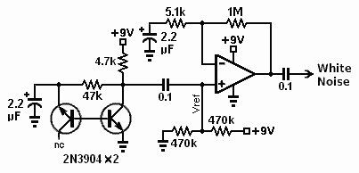
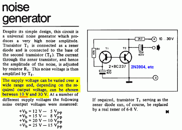
The 2-transistor noise circuit absolutely works at 9V. The variations in the published schematics are mainly in the value of the cap to ground from the "first" transistor's emitter.
The op amp in my schematic shouldn't be needed when driving a 1-transistor VCA as in the Tiny Dazzler circuit.
| Description: |
Mine. Op Amp is optional.
I didn't even really have to "select" the noisiest transistor. I tried two '3904s and one '2222 and they all sounded about the same. |
|
| Filesize: |
3.26 KB |
| Viewed: |
23199 Time(s) |
|
| Description: |
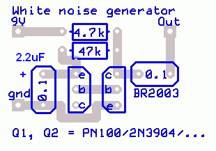
| I don't remember who posted this. Thanks, whoever you are. |
|
| Filesize: |
7.65 KB |
| Viewed: |
23200 Time(s) |
|
| Description: |
|
| Filesize: |
18.76 KB |
| Viewed: |
452 Time(s) |
| This image has been reduced to fit the page. Click on it to enlarge. |
|
_________________
Revenge is a dish best served with a fork... to the eye |
|
|
Back to top
|
|
 |
elmegil

Joined: Mar 20, 2012
Posts: 2179
Location: Chicago
Audio files: 16
|
 Posted: Fri Aug 08, 2014 10:21 am Post subject: Posted: Fri Aug 08, 2014 10:21 am Post subject:
|
  |
|
It sounds to me given the description that the problem is with the 1 Transistor VCA rather than the noise circuit....
The cap going to the next stage ought to block some of the lower frequency components and make the noise "more white". |
|
|
Back to top
|
|
 |
PHOBoS

Joined: Jan 14, 2010
Posts: 5881
Location: Moon Base
Audio files: 709
|
 Posted: Fri Aug 08, 2014 10:29 am Post subject: Posted: Fri Aug 08, 2014 10:29 am Post subject:
|
  |
|
| richardc64 wrote: | | The 2-transistor noise circuit absolutely works at 9V. |
 , I almost mentioned that you did get it to work. I've tried several different transistors (different types aswell as different ones of the same , I almost mentioned that you did get it to work. I've tried several different transistors (different types aswell as different ones of the same
type) but never got it working at 9V. And it was always a small increase in voltage that did it (it started working at 9.6V or something like that).
_________________
"My perf, it's full of holes!"
http://phobos.000space.com/
SoundCloud BandCamp MixCloud Stickney Synthyards Captain Collider Twitch YouTube |
|
|
Back to top
|
|
 |
Ruebezahl

Joined: Mar 09, 2014
Posts: 112
Location: Taiwan
Audio files: 4
|
 Posted: Sat Aug 09, 2014 4:19 pm Post subject: Posted: Sat Aug 09, 2014 4:19 pm Post subject:
|
  |
|
Thanks for the input. I tried the second circuit from richard. and there is no sound at all. since this part of the schematic is pretty much the same as in the original one, i really think, i am one of the persons where its not working with 9V, or maybe the transistor nowadays, are with reduced noise, and i got some of those, while the other people, who got it working, used other types (maybe being from different companys, although still being the same model). so now i have three choices.
1. get and try other transistors,
2. try it with an supply voltage of +12V (Was thinking about powering my drummachine with 12V anyway),
3. Maybe try alternative circuits with OpAmps instead of Transistors.
I think i go for the 12V Power Supply first, since i wanted to do it anyway. Lets see what happen. But i am excited, since its the first time i am gonna use a wallwart, instead of battery powered 
_________________
https://soundcloud.com/ruebezahl |
|
|
Back to top
|
|
 |
blue hell
Site Admin

Joined: Apr 03, 2004
Posts: 24513
Location: The Netherlands, Enschede
Audio files: 298
G2 patch files: 320
|
 Posted: Sat Aug 09, 2014 4:37 pm Post subject: Posted: Sat Aug 09, 2014 4:37 pm Post subject:
|
  |
|
| Ruebezahl wrote: |
1. get and try other transistors,
2. try it with an supply voltage of +12V (Was thinking about powering my drummachine with 12V anyway),
3. Maybe try alternative circuits with OpAmps instead of Transistors.
I think i go for the 12V Power Supply first, since i wanted to do it anyway. Lets see what happen. But i am excited, since its the first time i am gonna use a wallwart, instead of battery powered  |
2. is a good idea, 9 V is marginal for the reversed breeakdown to kick in 
1. you'll need to try a couple of transistors anyway
3. opamps wont help you, the transistor is used in a non-spec mode to get it to make the noise, and when it does it will have a decent amplitude anyway.
_________________
Jan
also .. could someone please turn down the thermostat a bit.
 |
|
|
Back to top
|
|
 |
blue hell
Site Admin

Joined: Apr 03, 2004
Posts: 24513
Location: The Netherlands, Enschede
Audio files: 298
G2 patch files: 320
|
 Posted: Sat Aug 09, 2014 4:52 pm Post subject: Posted: Sat Aug 09, 2014 4:52 pm Post subject:
|
  |
|
And what Scott just mentioned in the chat ...
4. when it works on 9V and the battery goes a tad low 
_________________
Jan
also .. could someone please turn down the thermostat a bit.
 |
|
|
Back to top
|
|
 |
Ruebezahl

Joined: Mar 09, 2014
Posts: 112
Location: Taiwan
Audio files: 4
|
 Posted: Sat Aug 09, 2014 5:50 pm Post subject: Posted: Sat Aug 09, 2014 5:50 pm Post subject:
|
  |
|
okay, so as soon as i can get the parts (monday) i will build a 12v power supply. One Question though: I saw that a lot of the schematics here are for +/-12V, with a virtual ground, i belive. I dont know much about that, but i would probably going for a power supply, wich is giving away +/-12V. Its compatible to circuits designed to work on a normal +12V Power Supply anyway, right? But what do I need to consider, when i have this +/- Power Supply, and a circuit wich is actually designed for a regular +12V. the point wich are connected to ground on the schematics, do i have to connect them to -12V or to 0V???
_________________
https://soundcloud.com/ruebezahl |
|
|
Back to top
|
|
 |
elmegil

Joined: Mar 20, 2012
Posts: 2179
Location: Chicago
Audio files: 16
|
 Posted: Sat Aug 09, 2014 5:51 pm Post subject: Posted: Sat Aug 09, 2014 5:51 pm Post subject:
|
  |
|
You could use 2 9V in series and get 18V  Might want to throw a smallish regulator to bring it down to say 15V.... Might want to throw a smallish regulator to bring it down to say 15V....
9V batteries don't have very good lifespan anyway though. |
|
|
Back to top
|
|
 |
elmegil

Joined: Mar 20, 2012
Posts: 2179
Location: Chicago
Audio files: 16
|
 Posted: Sat Aug 09, 2014 5:55 pm Post subject: Posted: Sat Aug 09, 2014 5:55 pm Post subject:
|
  |
|
| Ruebezahl wrote: | | okay, so as soon as i can get the parts (monday) i will build a 12v power supply. One Question though: I saw that a lot of the schematics here are for +/-12V, with a virtual ground, i belive. I dont know much about that, but i would probably going for a power supply, wich is giving away +/-12V. Its compatible to circuits designed to work on a normal +12V Power Supply anyway, right? But what do I need to consider, when i have this +/- Power Supply, and a circuit wich is actually designed for a regular +12V. the point wich are connected to ground on the schematics, do i have to connect them to -12V or to 0V??? |
you would want ground to be ground, -12V is really for bipolar op amps and similar things. Any power supply that has both, if you don' tneed -12V, you could just ditch the -12V part or not hook it to your circuit. |
|
|
Back to top
|
|
 |
Ruebezahl

Joined: Mar 09, 2014
Posts: 112
Location: Taiwan
Audio files: 4
|
 Posted: Sat Aug 09, 2014 6:11 pm Post subject: Posted: Sat Aug 09, 2014 6:11 pm Post subject:
|
  |
|
I am gonna do the 9V in series right away, stupid that i didn't think about that  To bring it down to 15V i just need to add a resistor after the positive pole, right? Any Suggestions for the size? To bring it down to 15V i just need to add a resistor after the positive pole, right? Any Suggestions for the size?
For the Power Supply: Okay that sounds like using the bipolar supply for other circuits should work just fine. So i think i will build one. Do you have any circuits, hopefully also with some explanation about setting up this kind of power supply. i cant google, since i dont know the proper word.
PS: This kind of bipolar power supply is NOT the same as alternating current, right?
_________________
https://soundcloud.com/ruebezahl |
|
|
Back to top
|
|
 |
elmegil

Joined: Mar 20, 2012
Posts: 2179
Location: Chicago
Audio files: 16
|
 Posted: Sat Aug 09, 2014 6:35 pm Post subject: Posted: Sat Aug 09, 2014 6:35 pm Post subject:
|
  |
|
| Ruebezahl wrote: | I am gonna do the 9V in series right away, stupid that i didn't think about that  To bring it down to 15V i just need to add a resistor after the positive pole, right? Any Suggestions for the size? To bring it down to 15V i just need to add a resistor after the positive pole, right? Any Suggestions for the size?
|
I think that would behave strangely. You can use a voltage divider to get a voltage drop, but that's generally not what it's for. I would use a 7815 regulator, probably the kind that comes in TOC-92 package (looks like a transistor) because this shouldn't have a lot of current requirement.
| Ruebezahl wrote: |
For the Power Supply: Okay that sounds like using the bipolar supply for other circuits should work just fine. So i think i will build one. Do you have any circuits, hopefully also with some explanation about setting up this kind of power supply. i cant google, since i dont know the proper word.
|
I would recommend spending some time perusing the circuits available at MusicFromOuterSpace.com. Ray has power supplies (including some kits), noise generators of various sorts, and lots of other goodies. He's also good about explaining things. Sometimes his circuits are a little more complex than strictly necessary, and I honestly don't care much for his style of schematic drawing, but it's an excellent resource nonetheless.
| Ruebezahl wrote: |
PS: This kind of bipolar power supply is NOT the same as alternating current, right? |
Absolutely! Often times bipolar supplies are fed from AC but it's not AC directly into your circuit, and if you're not familiar with mains wiring you should maybe avoid that. |
|
|
Back to top
|
|
 |
Ruebezahl

Joined: Mar 09, 2014
Posts: 112
Location: Taiwan
Audio files: 4
|
 Posted: Sat Aug 09, 2014 6:48 pm Post subject: Posted: Sat Aug 09, 2014 6:48 pm Post subject:
|
  |
|
well i just toasted my 74HC14-Clock while trying the 18V-thing. According to the datasheet, the supply voltage shouldn't exceed 6V. But it worked just fine with 9V so far...
So in the future, if i will use the 74HC14 as a clock, i guess i have to pull down the supplyvoltage for this IC seperately...
| Quote: | | I would recommend spending some time perusing the circuits available at MusicFromOuterSpace.com. Ray has power supplies (including some kits), noise generators of various sorts, and lots of other goodies. He's also good about explaining things. Sometimes his circuits are a little more complex than strictly necessary, and I honestly don't care much for his style of schematic drawing, but it's an excellent resource nonetheless. |
I will, i think i really need to learn more about power supplies. For me, its not really the fun part to think about this, but maybe one of the most important part.
| Quote: | | Absolutely! Often times bipolar supplies are fed from AC but it's not AC directly into your circuit, and if you're not familiar with mains wiring you should maybe avoid that. |
Oh, i will definitely stay away from AC, i have huge respect of this power coming out of my wall. i will just use it through wallwarts.
Thanks for your fast help so far!
_________________
https://soundcloud.com/ruebezahl |
|
|
Back to top
|
|
 |
elmegil

Joined: Mar 20, 2012
Posts: 2179
Location: Chicago
Audio files: 16
|
 Posted: Sat Aug 09, 2014 7:56 pm Post subject: Posted: Sat Aug 09, 2014 7:56 pm Post subject:
|
  |
|
| Ruebezahl wrote: | well i just toasted my 74HC14-Clock while trying the 18V-thing. According to the datasheet, the supply voltage shouldn't exceed 6V. But it worked just fine with 9V so far...
So in the future, if i will use the 74HC14 as a clock, i guess i have to pull down the supplyvoltage for this IC seperately...
|
Check into CMOS -- it has (almost?) all of the same functions as the 74 series but can generally take LOTS more voltage.
| Ruebezahl wrote: |
| Quote: | | I would recommend spending some time perusing the circuits available at MusicFromOuterSpace.com. Ray has power supplies (including some kits), noise generators of various sorts, and lots of other goodies. He's also good about explaining things. Sometimes his circuits are a little more complex than strictly necessary, and I honestly don't care much for his style of schematic drawing, but it's an excellent resource nonetheless. |
I will, i think i really need to learn more about power supplies. For me, its not really the fun part to think about this, but maybe one of the most important part.
|
Yup. Lots of non-glamorous parts to this addiction. I'm really not a fan of panel wiring, myself.
| Ruebezahl wrote: |
Oh, i will definitely stay away from AC, i have huge respect of this power coming out of my wall. i will just use it through wallwarts. |
So check out Ray's bipolar wall wart power supply.... There are a few others similar floating around as well (e.g. Frequency Central's: http://www.frequencycentral.co.uk/?page_id=894). |
|
|
Back to top
|
|
 |
-minus-
Joined: Oct 26, 2008
Posts: 787
Audio files: 13
|
 Posted: Sun Aug 10, 2014 12:09 am Post subject: Posted: Sun Aug 10, 2014 12:09 am Post subject:
|
  |
|
| Yes the transistor noise with the 47K and 4K7 resistors does work at 9V. I have had it working at less than 8V. You need to try different transistors of the same type and also test different types. I have had good results with 2N2222's 2N3904's and PN100's. |
|
|
Back to top
|
|
 |
richardc64

Joined: Jun 01, 2006
Posts: 679
Location: NYC
Audio files: 26
|
 Posted: Sun Aug 10, 2014 7:13 am Post subject: Posted: Sun Aug 10, 2014 7:13 am Post subject:
|
  |
|
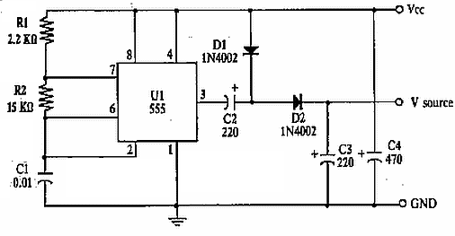
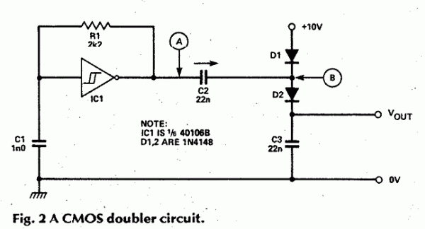
When all else fails, try a voltage doubler.
| -minus- wrote: | | Yes the transistor noise with the 47K and 4K7 resistors does work at 9V. I have had it working at less than 8V. You need to try different transistors of the same type and also test different types. I have had good results with 2N2222's 2N3904's and PN100's. |
Thank you. My experience was with an out-of-spec 7809 that delivered 8.7V.
| Description: |
|
| Filesize: |
9.89 KB |
| Viewed: |
22850 Time(s) |
|
| Description: |
| C2 & C3 seem kinda skimpy to me |
|
| Filesize: |
9.7 KB |
| Viewed: |
266 Time(s) |
| This image has been reduced to fit the page. Click on it to enlarge. |
|
| Description: |
|
| Filesize: |
7.1 KB |
| Viewed: |
315 Time(s) |
| This image has been reduced to fit the page. Click on it to enlarge. |

|
_________________
Revenge is a dish best served with a fork... to the eye |
|
|
Back to top
|
|
 |
drrainbows
Joined: Feb 06, 2015
Posts: 1
Location: vermont
|
 Posted: Fri Feb 06, 2015 10:42 am Post subject:
works Posted: Fri Feb 06, 2015 10:42 am Post subject:
works
Subject description: tiny dazzler |
  |
|
| I got this breadboarded and working on 12 volts. I find that it needs 9 volt or higher trigger pulse to activate the diode based envelope. Make sure to ground the clock pulse. It sounds great! I used the clock out from my 8 step sequencer to test it. It has a voltage pot on the clock out and will only trigger this circuit when turned up all the way. Hope that helps everyone. |
|
|
Back to top
|
|
 |
|

