| Author |
Message |
nuclearsound
Joined: Jul 16, 2013
Posts: 24
Location: Nantes, France
|
 Posted: Wed Aug 21, 2013 12:38 am Post subject: Posted: Wed Aug 21, 2013 12:38 am Post subject:
|
  |
|
Thanks Jumunius for your reply. But since I'm a beginner, what pins should I test on each IC ?
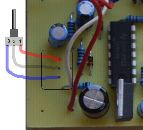
Another user asked for pictures, so find my hi-res pics if it's helpful :
http://dl.free.fr/b4A77O77q |
|
|
Back to top
|
|
 |
xpmtl

Joined: Aug 10, 2007
Posts: 162
Location: Brussels, Belgium
|
| Posted: Wed Aug 21, 2013 3:35 am Post subject:
|
|
|
For U1 : +5V at pin 7, GND at pin 4
For U2 : +5V at pin 4, GND at pin 11
For U3 : +5V at pin 4, GND at pin 11
For U4 : +5V at pin 7, GND at pin 4
Check that U100 (7805) is outputting +5V.
Which components are heating up?
Hum could be a bad ground connection.
_________________
http://sdiy.xpmtl.net |
|
|
Back to top
|
|
|
feggster
Joined: Sep 12, 2011
Posts: 52
Location: uk
|
|
|
Back to top
|
|
|
nuclearsound
Joined: Jul 16, 2013
Posts: 24
Location: Nantes, France
|
| Posted: Fri Aug 23, 2013 12:14 am Post subject:
|
|
|
Indeed, with that pot, it works...  The only thing now is that the output volume is reaaaaaaly low, even with the volume pot @ 100%. I plan to change R30 to a 330k or even 470k. But it seems so low that i can't imagine it could be enough. Just a quick question : are the pots current conductive ? Because I screwed them all on an iron plate on the back side. The only thing now is that the output volume is reaaaaaaly low, even with the volume pot @ 100%. I plan to change R30 to a 330k or even 470k. But it seems so low that i can't imagine it could be enough. Just a quick question : are the pots current conductive ? Because I screwed them all on an iron plate on the back side. |
|
|
Back to top
|
|
|
nuclearsound
Joined: Jul 16, 2013
Posts: 24
Location: Nantes, France
|
| Posted: Mon Aug 26, 2013 12:51 pm Post subject:
|
|
|
| Now I have no more hum with the insulation of the bottom of the box. And battery does not heat anymore. I changed R30 to 470k, sound is a bit higher, but still tiny. Will try the measurements. thanks |
|
|
Back to top
|
|
|
nuclearsound
Joined: Jul 16, 2013
Posts: 24
Location: Nantes, France
|
| Posted: Mon Aug 26, 2013 1:55 pm Post subject:
|
|
|
| One last thing, i didn't get by reading all pages of that topic, the use of C5. It says optional on my version of the bom, and I can't find its place on my PCB. Could it help to solder it somewhere ? |
|
|
Back to top
|
|
|
jumunius
Joined: Apr 19, 2010
Posts: 346
Location: San Francisco, CA
Audio files: 13
|
| Posted: Mon Aug 26, 2013 9:45 pm Post subject:
|
|
|
Hi, I asked Marc Bareille about this when I built mine. He said, "this one is optional . Mount it if the noise filter ( color) op-amp self oscillate ..."
I don't think there's a place for it on the board, you would just solder it to each end of R35. It won't make your unit any louder, it would just clean up some noise affecting the opamp I guess.
For what it's worth, Marc was really responsive whenever I had questions to ask him, so if you get stuck and aren't finding what you need here you might ask him as well.
_________________
-Jim |
|
|
Back to top
|
|
|
nuclearsound
Joined: Jul 16, 2013
Posts: 24
Location: Nantes, France
|
| Posted: Tue Aug 27, 2013 12:36 am Post subject:
|
|
|
| Thanks Jumunius for your reply. For Marc, I doubt he would be of any help, since he didn't reply my last e-mail back in June when I asked for a final doublecheck on my BOM. Hopefully this community will replace that. |
|
|
Back to top
|
|
|
jumunius
Joined: Apr 19, 2010
Posts: 346
Location: San Francisco, CA
Audio files: 13
|
| Posted: Tue Aug 27, 2013 12:34 pm Post subject:
|
|
|
| nuclearsound wrote: | | Thanks Jumunius for your reply. For Marc, I doubt he would be of any help, since he didn't reply my last e-mail back in June when I asked for a final doublecheck on my BOM. Hopefully this community will replace that. |
Ah, perhaps. Well, it's easy to let an email get beyond us now and again. I have gotten at least half a dozen replies from him over the years, so I wouldn't give up all hope. But if you're getting what you need here, all the better.
_________________
-Jim |
|
|
Back to top
|
|
|
nuclearsound
Joined: Jul 16, 2013
Posts: 24
Location: Nantes, France
|
| Posted: Tue Aug 27, 2013 4:40 pm Post subject:
|
|
|
| I just tested the UCs and all are fine. I also noticed since the beginning that the sound is mostly in the high frequencies range. I can obtain a low bass at the end of the VCO pot, but only an end, not in the middle. In other words, my DS-8 is more synth-ish than kick-ish. Don(t know if it can help to locate the problem. |
|
|
Back to top
|
|
|
jumunius
Joined: Apr 19, 2010
Posts: 346
Location: San Francisco, CA
Audio files: 13
|
| Posted: Tue Aug 27, 2013 10:23 pm Post subject:
|
|
|
| nuclearsound wrote: | | I just tested the UCs and all are fine. I also noticed since the beginning that the sound is mostly in the high frequencies range. I can obtain a low bass at the end of the VCO pot, but only an end, not in the middle. In other words, my DS-8 is more synth-ish than kick-ish. Don(t know if it can help to locate the problem. |
Earlier in the thread you mentioned you'd installed all Linear pots. The VCO is spec'd as log. Maybe just switching to Lin would solve it -- having the wrong pot can mean your response curve is wrong, which could mean that your range is right but it is hard to dial in the right result at one end of the spectrum.
_________________
-Jim |
|
|
Back to top
|
|
|
ikihsek
Joined: Nov 27, 2013
Posts: 1
Location: Leeds
|
| Posted: Wed Nov 27, 2013 9:36 am Post subject:
|
|
|
Hi all. New user here, found you guys after coming into some trouble with my DS7 clone, hope someone could help me out. I've built it the standard M.baraille way with a CA3080.
Basically there're drum synth sounds coming out but the Rate pot does nothing and the Mode pot is just acting as a pitch control. I noticed that the wiring for the Rate pot was reversed on the schematic from marcs site (R8 is connected to an outside lug AND wiper on the schem, but the hook-up diagram has the wiper+lug connection going into the LM324 and 47n cap). I swapped it to match the schematic and it worked! Fully funtional for about two day until it stopped during use, reverting back to the Rate pot problem. Tried swapping them back to the parts diagram way and still no Rate control.
I've thoroughly checked all the connections twice now, component to component rather than solder to solder so I'm pretty sure that's not a problem. Can't find any shorts. Have tried switching the LM324s which didn't change anything so I din't think theres anything wrong with them. Don't really know what to try next, any ideas?
The fact that it was fully funtional then just stopped is totally confusing me! |
|
|
Back to top
|
|
|
new voodoo
Joined: May 06, 2013
Posts: 94
Location: RVA USA
|
| Posted: Sat Nov 30, 2013 5:45 pm Post subject:
|
|
|
| ikihsek wrote: |
The fact that it was fully funtional then just stopped is totally confusing me! |
Yea sounds confusing to me as well..all I can think of is some sort of overage?
Perhaps also chek yr caps for failure?
Also, if you dont have one, you could build an audio tracer thingy. (Dont know whathe technical name is) Its perhaps an Audio Probe? Basically its just a audio wire with a connection you either can connect to an amp (3.5mm or 1/4") on one end (or a speaker, amp, etc) and a wire for connectn to ground and a probe wire with a clip or whatever with a capacitor soldered into the circ. Super simple, should take u maybe ten minutes to make and yuo can use it to trace audio being made at any point in the circuit by touching the wire clamp-y end thinagamajigger to a point anywhere on the lines and dots in a PCB. (sorry not really up on terminology)
hope that helps?
_________________
www.newvoodoodesign.com
-my creations, bends & bendable pieces
-vintage parts & tubes, IC's & audio chips
-oddities & weird
newvoodoo.blogspot.com
-bending DIY/projects
-crap |
|
|
Back to top
|
|
|
jumunius
Joined: Apr 19, 2010
Posts: 346
Location: San Francisco, CA
Audio files: 13
|
| Posted: Sun Dec 01, 2013 11:31 am Post subject:
|
|
|
| ikihsek wrote: | | I noticed that the wiring for the Rate pot was reversed on the schematic from marcs site (R8 is connected to an outside lug AND wiper on the schem, but the hook-up diagram has the wiper+lug connection going into the LM324 and 47n cap). |
Hi, I don't have any great advice except to say that this pot can be wired either way. It's a variable resistor. The wiper could link to either lug and it shouldn't have the effect of making the rate pot work or not. So the fact that the LFO started working for you after you did this is a red herring.
More likely, when you went to mess around with the wiring, you jostled something so that suddenly it was making a connection, and then eventually the connection failed again. I think you've said you already checked continuity from component to component. I assume this includes all the wiring as well. I'd try that again, especially for the rate and mode pots, and maybe jostle the wiring gently while you do it to see if it makes the continuity cut in and out especially on any connection.
_________________
-Jim |
|
|
Back to top
|
|
|
sneakthief

Joined: Jul 24, 2006
Posts: 569
Location: Berlin
|
| Posted: Sun Feb 16, 2014 1:45 pm Post subject:
|
|
|
For anyone that wants to convert a Coron DS7 to a DS8, I filled in the components overlay that was posted in this thread a long time ago:

(The 10K listed in bold italic was already stuffed on my DS7 board)
You have to remove the second foot-switch jack on the top next to the intensity pot and put in the "VCO/Noise Balance" pot.
You also need to drill 2 holes for the 2 new On-Off-On switches.
_________________
Sneak-Thief - raw electrofunk |
|
|
Back to top
|
|
|
burtondelfuturo
Joined: Jun 10, 2013
Posts: 4
Location: Buenos aires
|
|
|
Back to top
|
|
|
burtondelfuturo
Joined: Jun 10, 2013
Posts: 4
Location: Buenos aires
|
|
|
Back to top
|
|
|
jumunius
Joined: Apr 19, 2010
Posts: 346
Location: San Francisco, CA
Audio files: 13
|
Posted: Wed Mar 05, 2014 3:21 pm Post subject:
Re: trouble
Subject description: it doesn´t sound good |
|
|
| burtondelfuturo wrote: | hi,
All the ground to a single point, the jacks too
I use external 9v, negative ground
|
Are you actually wiring your grounds? It looks to me like some of your ground wires aren't even connected (for example, I see unconnected ground lugs of some pots and jacks). You need to solder every ground wire to ensure that everything is properly grounded.
_________________
-Jim |
|
|
Back to top
|
|
|
burtondelfuturo
Joined: Jun 10, 2013
Posts: 4
Location: Buenos aires
|
| Posted: Mon Mar 10, 2014 5:15 pm Post subject:
|
|
|
jumunius:
Thanks for your reply, the grounds are wiring with the metalic case, I will check it with the tester anyway. |
|
|
Back to top
|
|
|
Starspawn
Joined: Jun 14, 2013
Posts: 85
Location: Oslo
|
| Posted: Fri Jul 18, 2014 12:07 pm Post subject:
Help ... |
|
|
Well, Im in a little over my head.
Ive done quite a few stripboards lately, so decided Id try this (had all the parts  ), and went completely overboard with the double krunkus layout and 2 mutant DS7 expansion boards ... And it doesnt work. ), and went completely overboard with the double krunkus layout and 2 mutant DS7 expansion boards ... And it doesnt work.
Same silent VCO as others have reported, and I cant find a fault in the schematic or my work.
Sound is very low, so dont know if the VCA works, it might be just the negative input through 100k I hear.
I get the LFO waveforms on the scope, theyre ok, and I can route external cv and audio to the filter and affect the frequency (but still low volume).
So I suspect the expansion board is fine.
More sound with wave mix to the resonance side, so that as well suggest I get the filter mixed in but not the vco.
The connection diagram was sketchy, a few things like the VCO mods still needing their resistors, a few other small thing I got ... but still no luck.
Also slightly confused that UK moved the amps around.
C3 is removed as per the mutant mod, but as thats for the LFO range I dont see the problem.
C4 is 1n, C20 10uf, C1 3.3, C5 0.1uf, C6 1uf.
The ICs get the power theyre supposed to, theres continuity in the right places, parts should be fine ... dont know where to look :/
So stuck now, any hints?
Where does the VCO start and since It does get cv input there, what can I try to jumpstart it? Not even external CV works so its somehow the oscillation part. |
|
|
Back to top
|
|
|
Starspawn
Joined: Jun 14, 2013
Posts: 85
Location: Oslo
|
| Posted: Sat Jul 19, 2014 1:39 pm Post subject:
|
|
|
F**k yeah, after redrawing all the schematics from stripboard PCB and comparing to the supposedly correct schematics I well, found my own mistakes ...
Pitch but no control was the connection to the BC550 on the wrong line.
No envelopes was not having used the trimmer which is crucial to that (on the mutant stripboard), also using polycaps not ceramic was necessary.
Couple of bugs in my build still, but Ill figure it out, I think the guidelines are right, if a bit confusing and slightly off here and there (3.3 uf changed to 2.2 uf on mutant schematic for instance not mentioned elsewhere).
My last bugs is that one of the oscillators drifts up in pitch so some leak there somewhere, probably a small bridge, and other than that the amps is still just on really, I kind of wonder if the envelope trimming to fit the filter and pitch takes the amp cv input above its threshold of whatever.
A suspect there is that the mutant schematic has the trigger diode+NPN in another order than the stripboard.
Schematic is 5v then led to collector, trigger 100K to base, 2k2 emitter to ground.
Stripboard is 5v 2k2 to collector, base to 100K and trigger source, emitter to led to ground.
Maybe it needs a diode there so something doesnt leak back to the trigger output? |
|
|
Back to top
|
|
|
umschmitt

Joined: Jun 29, 2011
Posts: 189
Location: brrlin
Audio files: 11
|
| Posted: Sun Jul 20, 2014 2:51 am Post subject:
|
|
|
Hey, someone giving a try at the mutant DS-7 clone here! Congratulations!
The info i posted is quite chaotic, but mostly correct and my unit is still fully functional. Please keep in mind that i'm very far from being savvy!
| Starspawn wrote: | | No envelopes was not having used the trimmer which is crucial to that (on the mutant stripboard), also using polycaps not ceramic was necessary. |
Yep you have to find the sweet spot on the trimmer to achieve triggering, depending on the components around.
| Starspawn wrote: | | Couple of bugs in my build still, but Ill figure it out, I think the guidelines are right, if a bit confusing and slightly off here and there (3.3 uf changed to 2.2 uf on mutant schematic for instance not mentioned elsewhere). |
That could well be! I don't know you're referring to in this case, but most of the time values are not critical. It could change here the max. decay time for instance…
| Starspawn wrote: | A suspect there is that the mutant schematic has the trigger diode+NPN in another order than the stripboard.
Schematic is 5v then led to collector, trigger 100K to base, 2k2 emitter to ground.
Stripboard is 5v 2k2 to collector, base to 100K and trigger source, emitter to led to ground.
Maybe it needs a diode there so something doesnt leak back to the trigger output? |
Nooo nononono. Correct me if i'm wrong, but i think you're talking about the LED driver for triggering. First, you can just skip it, although it's always nice to have a lil'blinking LED on board. Nothing is leaking back in the trigger here (actually the use of the transistor is to prevent the LED to suck any current when lit). And yeah yeyeyeye you're right, i put components in a different order between the schem and the stripboard. But it doesn't make any difference whatsoever.
Please ask if you have more questions, but you seem to be on the way to having your circuit working!
And don't forget to try and experiment feeding both outputs in the other audio/mod. inputs. I suspect some sonic wilderness here!
_________________
::U::N::S::C::H::N::E::L::L:: |
|
|
Back to top
|
|
|
Starspawn
Joined: Jun 14, 2013
Posts: 85
Location: Oslo
|
| Posted: Sun Jul 20, 2014 3:38 am Post subject:
|
|
|
Hello, and thanks for supplying the schematics
For someone not super savvy thats great work and some good thinking.
And youre right, none of the mentioned deviations had any effect on my problems, which needed reflowing, cleaning etc
So all schematics have been confirmed correct so far.
Ive done all the mods except the feedback/trigger circuit because I ran out of room, but can still try it with patching/clippers instead.
The best part is having CV inputs really, the basic vco and lfo and filter is well, basic, but add a 3rd source of modulation and youre in business
Ive got both sides working as far as pitch and filter and so on goes now, only thing left is the volume envelopes.
Its always on regardless so I thought as the only thing changed there from the original was going from 22K to 1K by the trigger input, it would probably be there that the problem is?
The decay envelope (wired as in original schematic 1 and 2 to ground, 3 to that 1K) also hangs (trigger light stays on) when turned fully clockwise.
Why did you change it?
I think Ill just try a few different values there and see what happens ...
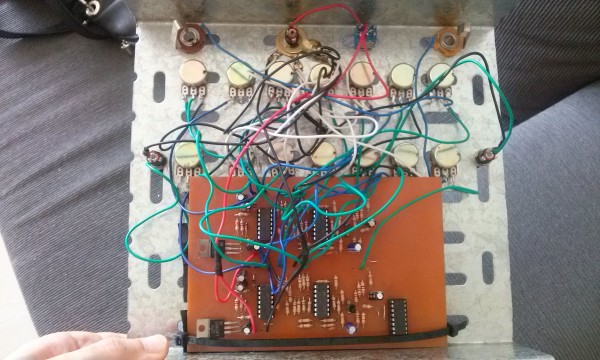
Heres a preliminary pic, also adding some very simple snare/hat circuits and a mixer.
 |
|
|
Back to top
|
|
|
Starspawn
Joined: Jun 14, 2013
Posts: 85
Location: Oslo
|
| Posted: Sun Jul 20, 2014 7:23 am Post subject:
|
|
|
And FIXED! Ill shame myself by describing how so its a lesson to other sloppy people.
Sometimes when the build has interconnected a bit beyond control and easy manipulation, and when its a stripboard design especially, the temptation to not take it apart, but just solder to the nearest resistor leg is big.
Thats what I did with the decay (and a bunch of others that were fine) ... on R1 cause it was on the same line as R3 and had easier legs to solder to ... offcourse I didnt see the cut between them from above, missed it looking at the stripboard and schematic because I didnt remember having done it, and didnt get it until the 5th pass (at least).
So dont do that.
Now:
PIIIOOOOU!
Thanks for making it all available people!
All contributions in thread confirmed working |
|
|
Back to top
|
|
|
umschmitt
Joined: Jun 29, 2011
Posts: 189
Location: brrlin
Audio files: 11
|
| Posted: Sun Jul 20, 2014 3:08 pm Post subject:
|
|
|
Good job!
Now you have no choice: you need to post more pics & soundclips!
(if you're looking for your toothbrush, i think i know where it is…)
_________________
::U::N::S::C::H::N::E::L::L:: |
|
|
Back to top
|
|
|
|

 Forum index » DIY Hardware and Software