| Author |
Message |
Uncle Krunkus
Moderator

Joined: Jul 11, 2005
Posts: 4761
Location: Sydney, Australia
Audio files: 52
G2 patch files: 1
|
 Posted: Tue Sep 23, 2008 3:06 am Post subject:
Precision +/-15V @ 1A PSU Posted: Tue Sep 23, 2008 3:06 am Post subject:
Precision +/-15V @ 1A PSU
Subject description: What I'd like to know is,...... |
  |
|
I'm working on a new precision +/-15V @ 1A PSU and I thought I'd share some pics and info on the process.
It's based on the LM723 (*2) regulator chip with MJE3055 transistors to carry the current load.
The schematic is freely available on the Elby Designs site. Here
I've done a stripboard layout of my own which I'll post if anyone is interested.
Please Note:
This DIY project involves the wiring of a mains transformer and associated IEC socket, fuse and switch. Attempting this without the proper precautions can be lethal!
If you have any doubts about your ability with mains potential wiring,... Do Not Attempt this Project.
No responsibility will be taken by myself or electro-music.com for anyone's ability or lack thereof to attempt a project of this nature.
I'll be posting some pics soon.
_________________
What makes a space ours, is what we put there, and what we do there.
Last edited by Uncle Krunkus on Fri Oct 10, 2008 4:28 am; edited 1 time in total |
|
|
Back to top
|
|
 |
etaoin

Joined: Jun 30, 2005
Posts: 761
Location: Utrecht, NL
|
| Posted: Tue Sep 23, 2008 5:42 am Post subject:
|
|
|
Thanks for reminding me of that one.
How easy would it be to pull out more amps? The MJE3055 can handle up to 10A so I guess the design is limiting in other places. I have some 2N3055 lying around that can do even more current.
_________________
http://www.casia.org/modular/ |
|
|
Back to top
|
|
|
fonik

Joined: Jun 07, 2006
Posts: 3950
Location: Germany
Audio files: 23
|
| Posted: Tue Sep 23, 2008 7:03 am Post subject:
|
|
|
the limitation is obviously the heat dissipation. take a look at these gorgeous heatsinks! 
i thought about a 1.5A PSU using the units case itself as heatsink. thoughts?
_________________

cheers,
matthias
____________
Big Boss at fonitronik
Tech Buddy at Random*Source |
|
|
Back to top
|
|
|
frijitz
Joined: May 04, 2007
Posts: 1734
Location: NM USA
Audio files: 54
|
Posted: Tue Sep 23, 2008 7:57 am Post subject:
Re: Precision +/-15V @ 1A PSU
Subject description: Build and Pics |
|
|
| Uncle Krunkus wrote: | I'm working on a new precision +/-15V @ 1A PSU and I thought I'd share some pics and info on the process.
It's based on the LM723 (*2) regulator chip with MJE3055 transistors to carry the current load. |
Interesting! How much better is this design than the LM317/LM337 regulator approach?

Ian |
|
|
Back to top
|
|
|
Peake

Joined: Jun 29, 2007
Posts: 1113
Location: Loss Angeles
Audio files: 3
|
| Posted: Tue Sep 23, 2008 9:11 am Post subject:
|
|
|
| fonik wrote: | | i thought about a 1.5A PSU using the units case itself as heatsink. thoughts? |
So long as the case doesn't flex at all, know that it's been done (with extra dissipation hardware). The Prophet 5 comes to mind, but that's where I saw the problem- the regulator ICs were bolted to the case, and the length of the case allowed for flexing- and the leads eventually break off at the PCB.
My knowing "it's been done" doesn't mean that it was totally successful. You'd have to look into any tales of the reliability of the P5 power supply to confirm.
_________________
We are selling emotions, there are no emotions in a grid. -mwagener
"IC 741. Sometimes you don't want fidelity." -Small Bear Electronics Catalog |
|
|
Back to top
|
|
|
bugbrand

Joined: Nov 27, 2005
Posts: 846
Location: Bristol, UK
Audio files: 1
G2 patch files: 1
|
|
|
Back to top
|
|
|
Uncle Krunkus
Moderator
Joined: Jul 11, 2005
Posts: 4761
Location: Sydney, Australia
Audio files: 52
G2 patch files: 1
|
| Posted: Tue Sep 23, 2008 2:59 pm Post subject:
|
|
|
I was going to elaborate on that.
This design will actually allow me to up the Amps later.
I'm putting in an 18-0-18 @ 4A4 per rail transformer.
Initially I'll use the 1A per rail circuit, but I'm also looking at a way of beefing up that circuit using a TIP29 and a 2N3055 on each rail. And yes, the trick is to fit the right heatsinking in. It should end up being able to deal with about 3A per rail.
Right from the start, I'm putting it all in a 2U rack case, and designing the layout with the upgrade in mind.
That's why I thought you guys might be interested. 
_________________
What makes a space ours, is what we put there, and what we do there. |
|
|
Back to top
|
|
|
Sine

Joined: Sep 10, 2007
Posts: 111
Location: Netherlands
|
| Posted: Tue Sep 23, 2008 4:20 pm Post subject:
|
|
|
I have built this thing and it is really rock solid with minimal drift
The only change I made is using darlington transistors so the 723 doesn't have to supply as much base current, something like the TIP140 or BDV65 would do nicely, or a MJ3001 if you must have a TO-3 in there |
|
|
Back to top
|
|
|
Uncle Krunkus
Moderator
Joined: Jul 11, 2005
Posts: 4761
Location: Sydney, Australia
Audio files: 52
G2 patch files: 1
|
| Posted: Tue Sep 23, 2008 4:24 pm Post subject:
|
|
|
That's one of the reasons for going with the TIP29/2N3055. I'm going to do them as a discrete darlington pair.
_________________
What makes a space ours, is what we put there, and what we do there. |
|
|
Back to top
|
|
|
Uncle Krunkus
Moderator
Joined: Jul 11, 2005
Posts: 4761
Location: Sydney, Australia
Audio files: 52
G2 patch files: 1
|
|
|
Back to top
|
|
|
Uncle Krunkus
Moderator
Joined: Jul 11, 2005
Posts: 4761
Location: Sydney, Australia
Audio files: 52
G2 patch files: 1
|
|
|
Back to top
|
|
|
Uncle Krunkus
Moderator
Joined: Jul 11, 2005
Posts: 4761
Location: Sydney, Australia
Audio files: 52
G2 patch files: 1
|
| Posted: Sat Sep 27, 2008 5:46 am Post subject:
|
|
|
Two shots of the power socket and fuse holder. Note the lug for attaching the chassis earth. Check with a meter that there is 0R from the lug to the other end of the panel.
| Description: |
|
| Filesize: |
160.89 KB |
| Viewed: |
165 Time(s) |
| This image has been reduced to fit the page. Click on it to enlarge. |

|
| Description: |
|
| Filesize: |
175.11 KB |
| Viewed: |
164 Time(s) |
| This image has been reduced to fit the page. Click on it to enlarge. |

|
_________________
What makes a space ours, is what we put there, and what we do there. |
|
|
Back to top
|
|
|
fluxmonkey
Joined: Jun 24, 2005
Posts: 708
Location: cleve
|
| Posted: Sat Sep 27, 2008 7:34 am Post subject:
|
|
|
i cant tell from the pics what kind of ventilation scheme you're using? big heatsinks help conduct the heat away from the regulators, but it's still got to have someplace to go... vent holes and/or forced air.
_________________
www.fluxmonkey.com |
|
|
Back to top
|
|
|
Sine
Joined: Sep 10, 2007
Posts: 111
Location: Netherlands
|
| Posted: Sat Sep 27, 2008 7:49 am Post subject:
|
|
|
Great work on the case Krunkus,
Yes, a step drill is a MUST for anyone that does diy electronics.
I build mine on matrix board

Originally for +-12V, but later modules needed +-15V so I did a "upgrade" on it a few months later |
|
|
Back to top
|
|
|
Uncle Krunkus
Moderator
Joined: Jul 11, 2005
Posts: 4761
Location: Sydney, Australia
Audio files: 52
G2 patch files: 1
|
| Posted: Sat Sep 27, 2008 7:58 am Post subject:
|
|
|
| bbob wrote: | | i cant tell from the pics what kind of ventilation scheme you're using? big heatsinks help conduct the heat away from the regulators, but it's still got to have someplace to go... vent holes and/or forced air. |
I'm not putting any ventilation holes at this stage, as this board is just 1Amp per rail. The 3A version (when it goes in) will have larger heatsinks and holes top and bottom. I'll sort out where to best place the holes once I have the larger heatsinks in place.
_________________
What makes a space ours, is what we put there, and what we do there. |
|
|
Back to top
|
|
|
Uncle Krunkus
Moderator
Joined: Jul 11, 2005
Posts: 4761
Location: Sydney, Australia
Audio files: 52
G2 patch files: 1
|
| Posted: Sat Sep 27, 2008 8:03 am Post subject:
|
|
|
I don't want to cut holes at the moment, 'cos I don't know where the larger heatsinks will be mounted. I've never built a PSU this size before, so I want to do a bit of testing under load and find out just how hot it gets.
_________________
What makes a space ours, is what we put there, and what we do there. |
|
|
Back to top
|
|
|
Sine
Joined: Sep 10, 2007
Posts: 111
Location: Netherlands
|
| Posted: Sat Sep 27, 2008 8:13 am Post subject:
|
|
|
| Personally I would ( and I have on my version ) mount the heatsinks on the back of the unit. |
|
|
Back to top
|
|
|
Uncle Krunkus
Moderator
Joined: Jul 11, 2005
Posts: 4761
Location: Sydney, Australia
Audio files: 52
G2 patch files: 1
|
| Posted: Sat Sep 27, 2008 5:44 pm Post subject:
|
|
|
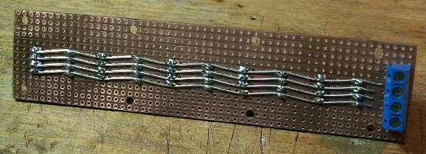
Here's the distribution board.
I used stripboard, as I'm going with the .1" pitch molex style keyed headers and plugs.
The screw terminals are reverse mounted, and jumpered over with a piece of .7mm tinned solid copper wire. I continued this along the stripboard to maintain the cross section and keep the resistance as low as possible. I thought about adding an extra 2 caps at the other end of the distribution board, but decided that would be overkill and would just up the inrush current. What do you guys think? I could still add them later if needed.
| Description: |
|
| Filesize: |
133.5 KB |
| Viewed: |
174 Time(s) |
| This image has been reduced to fit the page. Click on it to enlarge. |

|
| Description: |
|
| Filesize: |
125.05 KB |
| Viewed: |
155 Time(s) |
| This image has been reduced to fit the page. Click on it to enlarge. |

|
| Description: |
|
| Filesize: |
153.95 KB |
| Viewed: |
180 Time(s) |
| This image has been reduced to fit the page. Click on it to enlarge. |
|
_________________
What makes a space ours, is what we put there, and what we do there. |
|
|
Back to top
|
|
|
Uncle Krunkus
Moderator
Joined: Jul 11, 2005
Posts: 4761
Location: Sydney, Australia
Audio files: 52
G2 patch files: 1
|
| Posted: Sat Sep 27, 2008 5:48 pm Post subject:
|
|
|
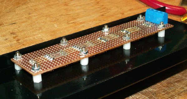
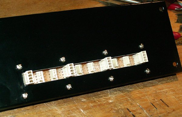
Then I mounted it in the slot with 6mm threaded plastic spacers. These are great, as they eliminate the "now, just hold on to those 5 things while I get this one in place,....doh!" effect. 
8 mounting points might seem a bit much, but it wasn't much harder than 4, and it means the board won't flex at all when connecting/disconnecting plugs.
I also kept it to one half of the panel depth, so I can add a second one later if need be.
| Description: |
|
| Filesize: |
164.49 KB |
| Viewed: |
161 Time(s) |
| This image has been reduced to fit the page. Click on it to enlarge. |
|
| Description: |
|
| Filesize: |
138.88 KB |
| Viewed: |
190 Time(s) |
| This image has been reduced to fit the page. Click on it to enlarge. |
|
_________________
What makes a space ours, is what we put there, and what we do there. |
|
|
Back to top
|
|
|
blue hell
Site Admin

Joined: Apr 03, 2004
Posts: 24422
Location: The Netherlands, Enschede
Audio files: 297
G2 patch files: 320
|
| Posted: Sat Sep 27, 2008 6:22 pm Post subject:
|
|
|
| Uncle Krunkus wrote: | | 8 mounting points might seem a bit much |
When you'd space them differently you could use less ... irregular placement is better than regular and having them at the end of the board is not the best position re. flex reduction .. funny thing is that it's really a musical problem of sorts, the eigen frequencies of the mounted board should be optimized for max stability at least cost sorry, good morning is what I really meant to say
_________________
Jan
also .. could someone please turn down the thermostat a bit.
 |
|
|
Back to top
|
|
|
Uncle Krunkus
Moderator
Joined: Jul 11, 2005
Posts: 4761
Location: Sydney, Australia
Audio files: 52
G2 patch files: 1
|
| Posted: Sat Sep 27, 2008 7:54 pm Post subject:
|
|
|
| Blue Hell wrote: | | When you'd space them differently you could use less ... irregular placement is better than regular and having them at the end of the board is not the best position re. flex reduction .. funny thing is that it's really a musical problem of sorts, the eigen frequencies of the mounted board should be optimized for max stability at least cost sorry, good morning is what I really meant to say |
Yeah, didn't you notice the gap in the middle is bigger?
_________________
What makes a space ours, is what we put there, and what we do there. |
|
|
Back to top
|
|
|
bugbrand
Joined: Nov 27, 2005
Posts: 846
Location: Bristol, UK
Audio files: 1
G2 patch files: 1
|
|
|
Back to top
|
|
|
Uncle Krunkus
Moderator
Joined: Jul 11, 2005
Posts: 4761
Location: Sydney, Australia
Audio files: 52
G2 patch files: 1
|
| Posted: Sun Sep 28, 2008 6:03 am Post subject:
|
|
|
| bugbrand wrote: | | Uncle K -- good work on the rectangular holes --- nice and tidy!! |
Yeah, that nibbling tool is one of the handiest things I've ever bought. Even more vital than a step drill IMHO. You hardly need to clean up the edges either, you can come right up to a line within less than .25mm. It does prefer aluminium to steel though, which is to be expected, but on a nice quality rack enclosure like this one, the front and back are aluminium which makes it easy.
_________________
What makes a space ours, is what we put there, and what we do there. |
|
|
Back to top
|
|
|
Luka

Joined: Jun 29, 2007
Posts: 1003
Location: Melb.
|
|
|
Back to top
|
|
|
Uncle Krunkus
Moderator
Joined: Jul 11, 2005
Posts: 4761
Location: Sydney, Australia
Audio files: 52
G2 patch files: 1
|
| Posted: Wed Oct 01, 2008 6:02 pm Post subject:
|
|
|
Yeah,
Hold on, I'll just tidy it up a bit.
_________________
What makes a space ours, is what we put there, and what we do there. |
|
|
Back to top
|
|
|
|

 Forum index » DIY Hardware and Software


