| Author |
Message |
davebr

Joined: Jun 09, 2007
Posts: 198
Location: portland, or
|
 Posted: Thu Jul 22, 2010 11:19 pm Post subject:
2010 Build Pictures Posted: Thu Jul 22, 2010 11:19 pm Post subject:
2010 Build Pictures
Subject description: Dave Brown modules |
  |
|
I've completed a number of Jurgen Haible, Thomas Henry, and other modules in 2010.
Top Row (left to right)
Haible Polymoog Resonator, Haible Scanner/Chorus Vibrato, Haible Frequency Shifter, and Haible Varislope Filter/Phaser
The holes in the center of the knobs on the Scanner/Chorus Vibrato are for the LED indicators. I used clear shaft potentiometers with the LEDs behind the potentiometers. I needed clear center knobs so I drilled holes and glued in an eyelet.
Bottom Row (left to right)
Buchla Lopass Gate, Henry VCLFO, Wogglebug, Henry VCO, Haible Living VCO
Information on all my modules is on my site.
http://modularsynthesis.com/
Dave

Last edited by davebr on Sat Jul 24, 2010 4:15 pm; edited 1 time in total |
|
|
Back to top
|
|
 |
sduck

Joined: Dec 16, 2007
Posts: 459
Location: Nashville
Audio files: 5
|
| Posted: Fri Jul 23, 2010 8:28 pm Post subject:
|
|
|
| Wow - great work! I'm especially fond of the frequency shifter design - it really breaks up the grid (in a good way)! |
|
|
Back to top
|
|
|
davebr
Joined: Jun 09, 2007
Posts: 198
Location: portland, or
|
Posted: Sat Jul 24, 2010 2:44 pm Post subject:
2010 Build Pictures
Subject description: Re: Dave Brown modules |
|
|
| sduck wrote: | | Wow - great work! I'm especially fond of the frequency shifter design - it really breaks up the grid (in a good way)! |
I try to use the smallest panel available, hence the significant use of the 3/4" knobs. It just isn't worth it to me to go to a larger panel size although I ended up with a 3U panel on the Living VCO and Varislope modules.
The challenge with the Frequency Shifter was fitting it all on a 2U panel along with nomenclature. I ended up using a layout that helped me group similar controls together.
top row is inputs
next triad/row is linear: fine, manual, fm
next triad/row is exponential: fine, range, fm
bottom row is output mix
Dave |
|
|
Back to top
|
|
|
sduck
Joined: Dec 16, 2007
Posts: 459
Location: Nashville
Audio files: 5
|
| Posted: Sat Jul 24, 2010 8:03 pm Post subject:
|
|
|
Yes. Maybe you remember - I liked it so much I copied it, with only small modifications to fit my panel design theme -
 |
|
|
Back to top
|
|
|
macumbista

Joined: Sep 12, 2007
Posts: 398
Location: berlin
Audio files: 3
|
| Posted: Wed Jul 28, 2010 12:09 pm Post subject:
|
|
|
More Neanderthal hand-hammered alu-plate panels hot off the bench. All electronics tested and working. Not at all pretty, but quite effective! Think I'm gonna freehand some analog computer circuits next...

Dual Serge 1973 Voltage Controlled Filter (CGS)
Dual Active Real Ring Modulator (CGS)
Quad Joystick Controller (Macumbista)
Quad Resonant Lopass Gate 292 (Buchla/T. White)
The 1973 VCF is quite sweet, I can really recommend it! I'm not satisfied with the RRM yet, I'm still working out some signal nulling issues. The joysticks--well they're joysticks...bipolar, no offset or scaling controls, buffered outputs, what more can you say?
The Lopass Gates surprised me simply because they just plain worked when I plugged them in. I was sure with four PCBs packed behind the panel and an assload of wiggly wiring, something had to go wrong. And somehow it didn't! They sound pretty good, but I haven't played around sending narrow pulses to them yet--need to build a comparator circuit for that first. Also haven't added the mixer board for the combined output yet, shhh don't tell anybody...
_________________
Esoteric drones and nonlinear distortion
Custom/handmade experimental instruments
macumbista.net |
|
|
Back to top
|
|
|
RF

Joined: Mar 23, 2007
Posts: 1502
Location: Northern Minnesota, USA
Audio files: 28
|
| Posted: Wed Jul 28, 2010 8:54 pm Post subject:
|
|
|
| macumbista wrote: | | Not at all pretty |
They look quite nice - I like them - Great Job!
bruce
_________________
www.sdiy.org/rfeng
"I want to make these sounds that go wooo-wooo-ah-woo-woo.”
(Herb Deutsch to Bob Moog ~1963) |
|
|
Back to top
|
|
|
macumbista
Joined: Sep 12, 2007
Posts: 398
Location: berlin
Audio files: 3
|
| Posted: Thu Jul 29, 2010 2:45 am Post subject:
|
|
|
| RF wrote: | | macumbista wrote: | | Not at all pretty |
They look quite nice - I like them - Great Job! |
Thanks Bruce! I just meant they aren't so slick as some of the panels I just saw on this thread. Big respect to those who have the time and patience to go the pro route. I'm always itchy to get them in the rack fast!
_________________
Esoteric drones and nonlinear distortion
Custom/handmade experimental instruments
macumbista.net |
|
|
Back to top
|
|
|
fonik

Joined: Jun 07, 2006
Posts: 3950
Location: Germany
Audio files: 23
|
| Posted: Thu Jul 29, 2010 2:54 am Post subject:
|
|
|
| macumbista wrote: | | Big respect to those who have the time and patience to go the pro route. I'm always itchy to get them in the rack fast! |
i am NOT patient and want to SAVE time. 
therefore i spend quite some money on those drilled and engraved schaeffer panels...
_________________

cheers,
matthias
____________
Big Boss at fonitronik
Tech Buddy at Random*Source |
|
|
Back to top
|
|
|
macumbista
Joined: Sep 12, 2007
Posts: 398
Location: berlin
Audio files: 3
|
| Posted: Thu Jul 29, 2010 3:07 am Post subject:
|
|
|
| fonik wrote: | i am NOT patient and want to SAVE time.
therefore i spend quite some money on those drilled and engraved schaeffer panels... |
I guess I could have said big respect to those with the fat wallets who go the pro route, but it doesn't sound so nice
Anyways, there's something very meditative about pounding and sanding the crap out of a piece of metal. It brings me inner peace!
_________________
Esoteric drones and nonlinear distortion
Custom/handmade experimental instruments
macumbista.net |
|
|
Back to top
|
|
|
emdot_ambient
Joined: Nov 22, 2009
Posts: 667
Location: Frederick, MD
|
Posted: Thu Jul 29, 2010 8:28 am Post subject:
Re: 2010 Build Pictures
Subject description: Dave Brown modules |
|
|
| davebr wrote: | | I've completed a number of Jurgen Haible, Thomas Henry, and other modules in 2010.... |
 Dude, I'm really not supposed to look at porn while I'm at work...but I can't help drooling over those modules! Dude, I'm really not supposed to look at porn while I'm at work...but I can't help drooling over those modules! |
|
|
Back to top
|
|
|
kkissinger
Stream Operator

Joined: Mar 28, 2006
Posts: 1452
Location: Kansas City, Mo USA
Audio files: 45
|
Posted: Thu Jul 29, 2010 9:31 am Post subject:
Re: 2010 Build Pictures
Subject description: Dave Brown modules |
|
|
| emdot_ambient wrote: | | davebr wrote: | | I've completed a number of Jurgen Haible, Thomas Henry, and other modules in 2010.... |
Dude, I'm really not supposed to look at porn while I'm at work...but I can't help drooling over those modules! |
Indeed. Beautiful work. Bravo!
_________________
-- Kevin
http://kevinkissinger.com |
|
|
Back to top
|
|
|
macumbista
Joined: Sep 12, 2007
Posts: 398
Location: berlin
Audio files: 3
|
| Posted: Fri Jul 30, 2010 7:21 am Post subject:
|
|
|
I don't know why I never built something like this sooner:

Fully documented here.
_________________
Esoteric drones and nonlinear distortion
Custom/handmade experimental instruments
macumbista.net |
|
|
Back to top
|
|
|
nerdware

Joined: Jul 11, 2009
Posts: 91
Location: UK
|
| Posted: Fri Jul 30, 2010 8:38 am Post subject:
|
|
|
| macumbista wrote: | | I don't know why I never built something like this sooner: |

_________________
http://soundcloud.com/nerdware/
"render unto digital what is due to digital, render unto analogue what is due to analogue" |
|
|
Back to top
|
|
|
kkissinger
Stream Operator
Joined: Mar 28, 2006
Posts: 1452
Location: Kansas City, Mo USA
Audio files: 45
|
| Posted: Sun Aug 01, 2010 6:39 pm Post subject:
A couple more CGS modules finished |
|
|
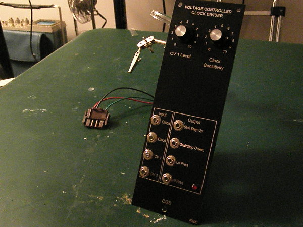
I finished the CGS Voltage-Controlled Clock Divider in time to demonstrate (and perform) with it last week at the Kansas City Regional electro-music festival.
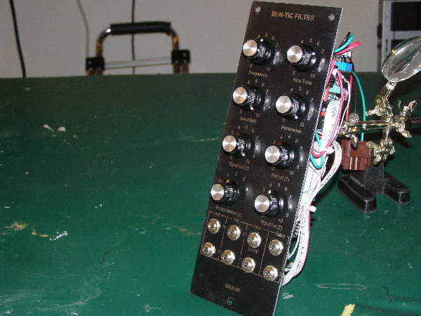
Today I finished the CGS Bi-N-Tic filter.
The Clock Divider worked on the first power-up. All I had to do was calibrate it.
The Bi-N-Tic was a little more challenging. The smoke test almost turned into a "real" smoke test... indeed, the SM311 chip heated up. Turns out that I had the FET in backwards. Turned it around and the module came to life. (It took me many hours to find it.)
I also tamed some of the voltages that feed the course frequency control (the design gives it a thirty volt range! I got it down to a more manageable 10 volt swing. 
How does it sound? Well once my studio is set up (I still haven't gotten everything back into place since the Kansas City EM festival) I'll post a demo track.
It is kind of a filter and oscillator combination that does amazing syncing effects and sometimes strange sweeps that sound more like a sample/hold. I really like the module and look forward to using it.
| Description: |
| The front panel of the CGS Voltage-Controlled Clock Divider. It is in a Aries 9"x3" module format. |
|
| Filesize: |
601.96 KB |
| Viewed: |
257 Time(s) |
| This image has been reduced to fit the page. Click on it to enlarge. |
|
| Description: |
| View that shows the PCB of the VC Clock Divider. |
|
| Filesize: |
503.47 KB |
| Viewed: |
242 Time(s) |
| This image has been reduced to fit the page. Click on it to enlarge. |

|
| Description: |
| The front panel of the CGS Bi-N-Tic filter. |
|
| Filesize: |
3.64 MB |
| Viewed: |
232 Time(s) |
| This image has been reduced to fit the page. Click on it to enlarge. |
|
| Description: |
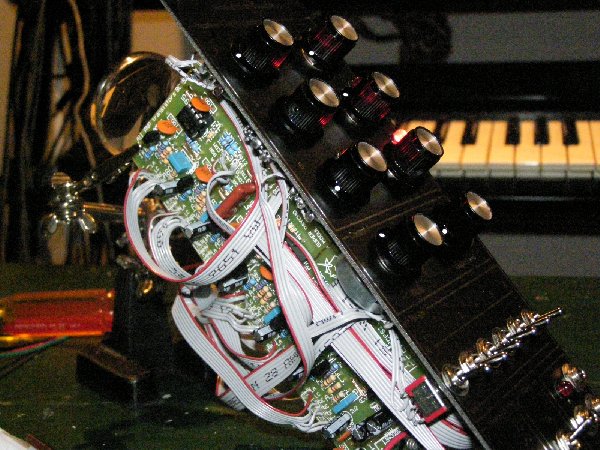
| The PCB of the Bi-N-Tic filter -- look at all the capacitors! |
|
| Filesize: |
3.88 MB |
| Viewed: |
240 Time(s) |
| This image has been reduced to fit the page. Click on it to enlarge. |

|
_________________
-- Kevin
http://kevinkissinger.com |
|
|
Back to top
|
|
|
RF
Joined: Mar 23, 2007
Posts: 1502
Location: Northern Minnesota, USA
Audio files: 28
|
| Posted: Sun Aug 01, 2010 7:02 pm Post subject:
|
|
|
Congrats Kevin!
The Bi-N-Tic is the _one_ module that sits forlorned on my shelf of shame. I have spent so much time on it it makes my head spin...and still no joy.
Maybe one of these days I'll get the motivation to go back to it....
bruce
_________________
www.sdiy.org/rfeng
"I want to make these sounds that go wooo-wooo-ah-woo-woo.”
(Herb Deutsch to Bob Moog ~1963) |
|
|
Back to top
|
|
|
kkissinger
Stream Operator
Joined: Mar 28, 2006
Posts: 1452
Location: Kansas City, Mo USA
Audio files: 45
|
| Posted: Sun Aug 01, 2010 8:31 pm Post subject:
Bi-N-Tic troubleshooting |
|
|
| RF wrote: | Congrats Kevin!
The Bi-N-Tic is the _one_ module that sits forlorned on my shelf of shame. I have spent so much time on it it makes my head spin...and still no joy.
Maybe one of these days I'll get the motivation to go back to it....
bruce |
Thanks, Bruce.
If you decide to revisit your Bi-N-Tic, perhaps you can start a troubleshooting thread on it.
I do have a volt/ohm meter, an oscilloscope, and oscillators on my Aries to use as signal injectors.
The circuit basically has three sections: the signal section, the clock, and the VCO. Suggest one starts with the signal section... even if the oscillator isn't running and the clock isn't clocking you will be able to get output and the bandpass and resonance (damping) will be effective. If you apply an input signal at "in" you should see the signal at pin 6 of each of the LF356 op-amps. If you have a signal at pin 6 of IC4, and no signal from your output, then your output may be connected to the wrong place on the board.
From there, it is a matter of working backwards -- you can inject a pulse signal for the clock.. if the clock chip works, then you move backwards to the VCO.
To check the clock, you can simply take an external clock signal and apply it to pin 6 of the CA3140. If the clock is working, your output signal will be modulated according to the clock frequency.
If the VCO is working, you should see an AC signal at pin 6 of the CA3140.
If there is no oscillation, then scrutinize the FET. Note that the MPF102 (a common FET) doesn't work too well (according the instructions). Also, check its polarity (mine was reversed and not only was there no oscillation, it was shorting the LM311 chip -- the LM311 heated up!)
Be aware that if you substituted 2N3904's and 2N3906's for the BC... transistors, you must install them with the polarity reversed from that on the board. (But, as I found out, though I substituted an FET, I should not have reversed it).
You can also apply a signal to your CV input and see if it appears at pin 7 of the TL072. The front panel frequency controls should cause the voltage at pin 7 to swing. Note that the CV signal at the tempco resistor is extremely attenuated (due to the 56K resistor). However, the LM394 pair amplifies it and you should see a healthy signal coming off of them.
OK, I hope this helps a little... I thought I'd type this out while it is fresh on my mind.
I hope you can bring your Bi-N-Tic to life sometime. It is a really cool module.
_________________
-- Kevin
http://kevinkissinger.com |
|
|
Back to top
|
|
|
TekniK

Joined: Aug 10, 2008
Posts: 1059
|
| Posted: Sun Aug 01, 2010 9:14 pm Post subject:
|
|
|
| nice wiring,i like the use of those flat cables |
|
|
Back to top
|
|
|
AnalogCustom

Joined: Jun 23, 2009
Posts: 52
Location: Chile
|
| Posted: Mon Aug 02, 2010 12:22 am Post subject:
|
|
|
| macumbista wrote: | More Neanderthal hand-hammered alu-plate panels hot off the bench. All electronics tested and working. Not at all pretty, but quite effective! Think I'm gonna freehand some analog computer circuits next...
Dual Serge 1973 Voltage Controlled Filter (CGS)
Dual Active Real Ring Modulator (CGS)
Quad Joystick Controller (Macumbista)
Quad Resonant Lopass Gate 292 (Buchla/T. White)
The 1973 VCF is quite sweet, I can really recommend it! I'm not satisfied with the RRM yet, I'm still working out some signal nulling issues. The joysticks--well they're joysticks...bipolar, no offset or scaling controls, buffered outputs, what more can you say?
The Lopass Gates surprised me simply because they just plain worked when I plugged them in. I was sure with four PCBs packed behind the panel and an assload of wiggly wiring, something had to go wrong. And somehow it didn't! They sound pretty good, but I haven't played around sending narrow pulses to them yet--need to build a comparator circuit for that first. Also haven't added the mixer board for the combined output yet, shhh don't tell anybody... |
Genial !!
MA. |
|
|
Back to top
|
|
|
nerdware
Joined: Jul 11, 2009
Posts: 91
Location: UK
|
| Posted: Mon Aug 02, 2010 3:07 am Post subject:
Re: A couple more CGS modules finished |
|
|
| kkissinger wrote: | I finished the CGS Voltage-Controlled Clock Divider in time to demonstrate (and perform) with it last week at the Kansas City Regional electro-music festival.
Today I finished the CGS Bi-N-Tic filter.
|
Very tasty. I'm reminded strongly of the early Digisound 80 panels, esp on the Clock Divider. No tick marks, just numerals.
I sometimes wonder, when I look at a new module, what it would look like behind a Digisound panel. 
_________________
http://soundcloud.com/nerdware/
"render unto digital what is due to digital, render unto analogue what is due to analogue" |
|
|
Back to top
|
|
|
macumbista
Joined: Sep 12, 2007
Posts: 398
Location: berlin
Audio files: 3
|
| Posted: Tue Aug 03, 2010 5:58 pm Post subject:
|
|
|

This module allows “Buchlidian” style processing of three input voltages. It can do much of what the original Buchla 257 Voltage Processor does: addition, subtraction, multiplication and division. The only feature of the 257 it lacks is the ability to “transfer control” (i.e. interpolate) between the two different applied voltages.
It contains one section with three "attenuverting"/bipolar inputs. The other section contains an analog multiplier. The panel contains two of each section. The X and Y inputs can be switched between AC and DC coupling, while the Z input is always DC coupled.
Full documentation including schematic here.
_________________
Esoteric drones and nonlinear distortion
Custom/handmade experimental instruments
macumbista.net |
|
|
Back to top
|
|
|
kkissinger
Stream Operator
Joined: Mar 28, 2006
Posts: 1452
Location: Kansas City, Mo USA
Audio files: 45
|
| Posted: Wed Aug 04, 2010 9:24 pm Post subject:
A new Super Psycho Modulation Source |
|
|
Those who attended the Kansas City electro-music festival may recognize this panel -- indeed, this is the panel that I used to demo the DecalPro process (though I had to redo the label -- I didn't spray enough glue on the decal and it didn't completely stick to the panel).
It is actually quite a simple device -- six square wave oscillators all mixed together. Each oscillator has its own frequency control, and a switch for off, audio frequency, and low frequency. Oscillators 1 and 2 can be converted to triangle waves.
All the oscillators are fed to an op-amp mixer which, in turn, is passed through a lag (glide) circuit that has a variable control and a switch.
It works very well in conjunction with my (seperate) voltage-quantizer module to create random melodies. In the audio range, it can produce drones -- however it is very powerful when used as an FM source for another VCO. After all -- with six different oscillators, some very complex sounds are possible -- ranging from noise/static sounds to very rich drones.
| Description: |
| The front panel of the Super Psycho Modulation Source. |
|
| Filesize: |
208.25 KB |
| Viewed: |
232 Time(s) |
| This image has been reduced to fit the page. Click on it to enlarge. |

|
| Description: |
| View of the circuit board. This module, for its size, has a lot of wiring. The front panel has a total of 27 Pots, LEDs, switches, and jacks -- as dense a layout as the Klee Sequencer! I leave sufficient slack in the wiring that I can easily troublesho |
|
| Filesize: |
1.19 MB |
| Viewed: |
214 Time(s) |
| This image has been reduced to fit the page. Click on it to enlarge. |
|
_________________
-- Kevin
http://kevinkissinger.com |
|
|
Back to top
|
|
|
kkissinger
Stream Operator
Joined: Mar 28, 2006
Posts: 1452
Location: Kansas City, Mo USA
Audio files: 45
|
Posted: Thu Aug 05, 2010 9:51 am Post subject:
Re: 2010 Build Pictures
Subject description: Dave Brown modules |
|
|
From Dave's site:
| Quote: | | I have been building my modular synthesizer since 2001. It now consists of 95 modules. |
Just took a look at your site -- wow!
_________________
-- Kevin
http://kevinkissinger.com |
|
|
Back to top
|
|
|
kkissinger
Stream Operator
Joined: Mar 28, 2006
Posts: 1452
Location: Kansas City, Mo USA
Audio files: 45
|
| Posted: Thu Aug 05, 2010 9:56 am Post subject:
|
|
|
@sduck and macumbista --
I really like those colorful panels.
Since I'm currently expanding my Aries synth, I have stuck with their simple color scheme.
On my wish-list is an integrated theremin/synthesizer and it will have pretty colors for the labeling.
_________________
-- Kevin
http://kevinkissinger.com |
|
|
Back to top
|
|
|
macumbista
Joined: Sep 12, 2007
Posts: 398
Location: berlin
Audio files: 3
|
| Posted: Thu Aug 05, 2010 11:16 am Post subject:
|
|
|
| TekniK wrote: | | nice wiring,i like the use of those flat cables |
I've used both flat wiring and wrapped wires in my builds (see the last front/back photo of the multiplier I posted a few days ago for the wrapped wire version). I noticed particularly on an 8x8 matrix mixer I built that parallel flat cables tend to give a lot more cross-talk between the channels. Am I alone in this discovery?
_________________
Esoteric drones and nonlinear distortion
Custom/handmade experimental instruments
macumbista.net |
|
|
Back to top
|
|
|
TekniK
Joined: Aug 10, 2008
Posts: 1059
|
| Posted: Thu Aug 05, 2010 2:14 pm Post subject:
|
|
|
| macumbista wrote: | | TekniK wrote: | | nice wiring,i like the use of those flat cables |
I've used both flat wiring and wrapped wires in my builds (see the last front/back photo of the multiplier I posted a few days ago for the wrapped wire version). I noticed particularly on an 8x8 matrix mixer I built that parallel flat cables tend to give a lot more cross-talk between the channels. Am I alone in this discovery? |
hmm,no i heard from several users the Semtex from anyware is full of crosstalk and i guess its from the use of flatcables
in a jupiter 8 there are also big flat cables and no crosstalk..
but i guess there most be a big difference between the electronic engineers skills from roland and the anyware guy lol |
|
|
Back to top
|
|
|
|

 Forum index » DIY Hardware and Software
