| Author |
Message |
dingebre

Joined: Aug 10, 2008
Posts: 270
Location: Salt Lake City, UT USA
|
 Posted: Fri Apr 10, 2009 10:23 pm Post subject:
FracRack panel Posted: Fri Apr 10, 2009 10:23 pm Post subject:
FracRack panel |
  |
|
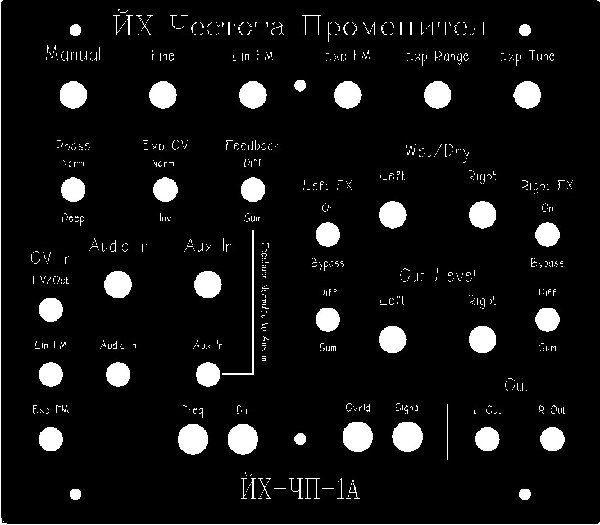
Last update I hope.
I've uploaded one last version. I got rid of the Mic/Line jack and am just using an auxiliary in and an "Audio" in. The only difference is the Aux in is normaled to the feedback (per JH's connection diagram). The "Audio in" bypasses the mic pre-amp and is a simple unbalanced input (similar to what Dave Brown did I think).
I also relabeled and reorganized the knobs to make more sense, I hope. Instead of up/down, or on/off, I used sum or diff as this was what the switches are connected to.
I've sent this one off to Schaffer for building.
Again, I used Bulgarian for the name, JH Frequency Shifter, and JH-FS-1
Thanks JH for some truly amazing projects.
David
| Description: |
|
| Filesize: |
109.13 KB |
| Viewed: |
483 Time(s) |
| This image has been reduced to fit the page. Click on it to enlarge. |
|
| Description: |
|

Download (listen) |
| Filename: |
Blacet JH Shifter rev 2 no mic.fpd |
| Filesize: |
2.27 KB |
| Downloaded: |
477 Time(s) |
_________________
David M. Ingebretsen, M.S., M.E.
Collision Forensics & Enginering, Inc.
dingebre@3dphysics.net
http://www.xmission.com/~dingebre/Synthasystem.html |
|
|
Back to top
|
|
 |
xpmtl

Joined: Aug 10, 2007
Posts: 162
Location: Brussels, Belgium
|
| Posted: Mon Apr 20, 2009 5:10 am Post subject:
Re: My panel design |
|
|
| lexvortex wrote: | Hi,
Here is my panel design. It's based off Marc B's beautiful design  with a few changes. So far I've just got the panel stuffed and the PCBs fully stuffed and now all I need is a little time to wire it up! with a few changes. So far I've just got the panel stuffed and the PCBs fully stuffed and now all I need is a little time to wire it up!
Cheers,
Dave |
Hi Lexvortex,
Do you mind sharing your .fpd file?
that's the design i'm after and i don't feel like reinventing the wheel 
_________________
http://sdiy.xpmtl.net
Last edited by xpmtl on Mon Apr 20, 2009 3:37 pm; edited 1 time in total |
|
|
Back to top
|
|
|
lexvortex

Joined: May 14, 2008
Posts: 155
Location: Toronto
|
| Posted: Mon Apr 20, 2009 11:20 am Post subject:
|
|
|
Hi,
I'm about half way through wiring my freq shifter up and have a few questions:
1. For the APFout, 1inv, INVout, and *cmp_out, where would I connect them to ground? is it necessary to connect them to ground?
2. What is the difference between the Freq LED and the DIR LED, I would think they are similar but would like some clarification.
Thanks for the help 
Dave |
|
|
Back to top
|
|
|
jhaible

Joined: May 25, 2007
Posts: 2014
Location: Germany
Audio files: 24
|
| Posted: Mon Apr 20, 2009 2:26 pm Post subject:
|
|
|
| lexvortex wrote: |
1. For the APFout, 1inv, INVout, and *cmp_out, where would I connect them to ground? is it necessary to connect them to ground?
|
No GND connections needed here; see http://www.jhaible.de/fs1a/jh_fs1a_schematics_connections_3.pdf for details.
| Quote: | 2. What is the difference between the Freq LED and the DIR LED, I would think they are similar but would like some clarification.
|
Freq LED flashes with the rate of the modulation oscillator. Dir Led shows oscillator spinning forward or backward.
JH.
_________________
"I tell you the truth, if anyone says to this mountain, 'Go, throw yourself into the sea,' and does not doubt in his heart but believes that what he says will happen, it will be done for him. Therefore I tell you, whatever you ask for in prayer, believe that you have received it, and it will be yours." (Mk 11,23f) |
|
|
Back to top
|
|
|
lexvortex
Joined: May 14, 2008
Posts: 155
Location: Toronto
|
| Posted: Tue Apr 21, 2009 6:27 pm Post subject:
|
|
|
Hi JH,
Thanks for the help I just finished wiring it up (wow  , this has to be one of the most challenging projects yet!!), now to try and calibrate it and see if I managed to get it right , this has to be one of the most challenging projects yet!!), now to try and calibrate it and see if I managed to get it right
Cheers,
Dave |
|
|
Back to top
|
|
|
lexvortex
Joined: May 14, 2008
Posts: 155
Location: Toronto
|
| Posted: Thu Apr 23, 2009 9:34 pm Post subject:
Need Help |
|
|
Hi JH,
I finally fired up my Fsa1 to try and calibrate it and right away there were problems 
I hooked up the oscilloscope as shown in the diagram and turned on the power and I got one tri wave on probe 1 and probe 2 was flat lined. I turned it off and checked all the wiring and took each board out and checked for correct parts placements and correct IC's and diode's pointing the right way etc.
When I turn the manual knob the freq doesn't change, when it passes through zero the tri wave jumps a bit. The freq LED initially is unlit then goes on and stay on. None of the ICs get hot either.
I tried passing audio through the input and aux input and I get the same signal on both outputs. The input knobs (main in and aux) change the volume, and turning the pot to full mix makes the signal disappear.
Where should I start looking for problems, theres a lot to search through on this board, maybe voltages to certain IC's? I'm kinda lost as to where to start with project, I've built a lot of other projects and got them all working so I know with a little patience and some help I'll get this going too.
Is there anything specific that I can tell you that would help you help me?
Any help would be greatly appreciated
Thank you,
Dave |
|
|
Back to top
|
|
|
jhaible
Joined: May 25, 2007
Posts: 2014
Location: Germany
Audio files: 24
|
| Posted: Fri Apr 24, 2009 2:12 am Post subject:
Re: Need Help |
|
|
| lexvortex wrote: | Hi JH,
I hooked up the oscilloscope as shown in the diagram and turned on the power and I got one tri wave on probe 1 and probe 2 was flat lined.
|
Tracing the signal along the VCO structure:
U8, pin 7: triangle. (You have that.)
U9, pin 7: triangle - yes or no?
U9, pin 7: square wave - yes or no?
U8, pin 1 : triangle (this is flat - right?)
Are the power rails ok on every IC? (+/-15V)
| Quote: | | When I turn the manual knob the freq doesn't change, |
Looks like a second, separate problem.
| Quote: | | I tried passing audio through the input and aux input and I get the same signal on both outputs. The input knobs (main in and aux) change the volume, and turning the pot to full mix makes the signal disappear. |
That's to be expected with the VCO not working.
So let's trace this first (see above).
JH.
_________________
"I tell you the truth, if anyone says to this mountain, 'Go, throw yourself into the sea,' and does not doubt in his heart but believes that what he says will happen, it will be done for him. Therefore I tell you, whatever you ask for in prayer, believe that you have received it, and it will be yours." (Mk 11,23f) |
|
|
Back to top
|
|
|
lexvortex
Joined: May 14, 2008
Posts: 155
Location: Toronto
|
| Posted: Fri Apr 24, 2009 2:04 pm Post subject:
|
|
|
Hi JH,
Thanks for the quick reply I checked all the voltages at ICs and they are all +-15V and the THAT1510 IC was +-14V. I didn't see which pin to test for a V+ for the LM1496N IC from the data sheet.
Tracing the signal along the VCO structure:(U9, pin 7 is listed twice)
U8, pin 7: triangle. (You have that.)----yes was a triangle
U9, pin 7: triangle - yes or no?-----yes is a triangle (U9 pin7)
U9, pin 7: square wave - yes or no?-----is the same pin as above a triangle(U9 pin 7)
U8, pin 1 : triangle (this is flat - right?) -----yes is still flat line
What should I check for next? I tried replacing C7, but that did nothing.
Thanks again,
Dave |
|
|
Back to top
|
|
|
jhaible
Joined: May 25, 2007
Posts: 2014
Location: Germany
Audio files: 24
|
| Posted: Fri Apr 24, 2009 2:28 pm Post subject:
|
|
|
| lexvortex wrote: | Hi JH,
Thanks for the quick reply I checked all the voltages at ICs and they are all +-15V and the THAT1510 IC was +-14V. I didn't see which pin to test for a V+ for the LM1496N IC from the data sheet.
Tracing the signal along the VCO structure:(U9, pin 7 is listed twice)
U8, pin 7: triangle. (You have that.)----yes was a triangle
U9, pin 7: triangle - yes or no?-----yes is a triangle (U9 pin7)
U9, pin 7: square wave - yes or no?-----is the same pin as above a triangle(U9 pin 7)
U8, pin 1 : triangle (this is flat - right?) -----yes is still flat line
What should I check for next? I tried replacing C7, but that did nothing.
Thanks again,
Dave |
Tracing the signal along the VCO structure:(U9, pin 7 is listed twice)
U8, pin 7: triangle. (You have that.)----yes was a triangle
U9, pin 7: triangle - yes or no?-----yes is a triangle (U9 pin7)
U9, pin 1: square wave - yes or no?
Pin 1 - My fault - that was a typo. Square wave?
JH.
_________________
"I tell you the truth, if anyone says to this mountain, 'Go, throw yourself into the sea,' and does not doubt in his heart but believes that what he says will happen, it will be done for him. Therefore I tell you, whatever you ask for in prayer, believe that you have received it, and it will be yours." (Mk 11,23f) |
|
|
Back to top
|
|
|
lexvortex
Joined: May 14, 2008
Posts: 155
Location: Toronto
|
| Posted: Fri Apr 24, 2009 2:35 pm Post subject:
|
|
|
Hi JH,
Yes I get a square wave at U9 pin 1.
Thanks,
Dave |
|
|
Back to top
|
|
|
jhaible
Joined: May 25, 2007
Posts: 2014
Location: Germany
Audio files: 24
|
| Posted: Fri Apr 24, 2009 2:57 pm Post subject:
|
|
|
| lexvortex wrote: | Hi JH,
Yes I get a square wave at U9 pin 1.
Thanks,
Dave |
All right, then I suspect an errir around U7A.
(http://www.jhaible.de/fs1a/jh_fs1a_schematics_board_1.pdf)
Pin 3 of this OTA must see approx. +/-3.5V square wave.
Voltage accross R29 and R30 must be approximately the same.
Both should change when the VCO Frequency is altered.
JH.
_________________
"I tell you the truth, if anyone says to this mountain, 'Go, throw yourself into the sea,' and does not doubt in his heart but believes that what he says will happen, it will be done for him. Therefore I tell you, whatever you ask for in prayer, believe that you have received it, and it will be yours." (Mk 11,23f) |
|
|
Back to top
|
|
|
lexvortex
Joined: May 14, 2008
Posts: 155
Location: Toronto
|
| Posted: Sat Apr 25, 2009 11:12 am Post subject:
|
|
|
Hi JH,
I was checking everything around the U7a IC and I found my first error in the build, somehow I put 30.6K resistors in for every 30K spot! So now I'm gonna switch them all out and see where that leads me  I hope this may fix something I hope this may fix something
| Quote: | Pin 3 of this OTA must see approx. +/-3.5V square wave.
Voltage accross R29 and R30 must be approximately the same.
Both should change when the VCO Frequency is altered.
|
There is a +-3.5V square wave here too. As for the voltage across the two resistors, I couldn't get a solid reading, maybe I'm doing it wrong, I just put the voltmeter across the resistor right?
I'll get back to you when I get all the 30K replaced.
Thanks,
Dave |
|
|
Back to top
|
|
|
jhaible
Joined: May 25, 2007
Posts: 2014
Location: Germany
Audio files: 24
|
| Posted: Sat Apr 25, 2009 11:46 am Post subject:
|
|
|
| lexvortex wrote: | Hi JH,
I was checking everything around the U7a IC and I found my first error in the build, somehow I put 30.6K resistors in for every 30K spot! So now I'm gonna switch them all out and see where that leads me I hope this may fix something
| Quote: | Pin 3 of this OTA must see approx. +/-3.5V square wave.
Voltage accross R29 and R30 must be approximately the same.
Both should change when the VCO Frequency is altered.
|
There is a +-3.5V square wave here too. As for the voltage across the two resistors, I couldn't get a solid reading, maybe I'm doing it wrong, I just put the voltmeter across the resistor right?
I'll get back to you when I get all the 30K replaced.
Thanks,
Dave |
Don't replace these resistors - that's just 2% off and shouldn't hurt.
But maybe there are similar errors elsewhere- If a resistor is by one order of magnitude off (150k instead of 15k) - such errors could be serious.
JH.
_________________
"I tell you the truth, if anyone says to this mountain, 'Go, throw yourself into the sea,' and does not doubt in his heart but believes that what he says will happen, it will be done for him. Therefore I tell you, whatever you ask for in prayer, believe that you have received it, and it will be yours." (Mk 11,23f) |
|
|
Back to top
|
|
|
lexvortex
Joined: May 14, 2008
Posts: 155
Location: Toronto
|
| Posted: Sat Apr 25, 2009 12:53 pm Post subject:
|
|
|
Hi JH,
I double checked each resistor "whew", and they all are the correct value. Should I try replacing the LM13700N (U7)? I don't want to blow another one if the problem lies elsewhere but maybe it's safe to try?
I'm still not sure about the resistors R29-30, should I be seeing +-3.5V?
Thanks again,
Dave |
|
|
Back to top
|
|
|
jhaible
Joined: May 25, 2007
Posts: 2014
Location: Germany
Audio files: 24
|
| Posted: Sat Apr 25, 2009 1:31 pm Post subject:
|
|
|
| lexvortex wrote: | Hi JH,
I double checked each resistor "whew", and they all are the correct value. Should I try replacing the LM13700N (U7)? I don't want to blow another one if the problem lies elsewhere but maybe it's safe to try?
I'm still not sure about the resistors R29-30, should I be seeing +-3.5V?
Thanks again,
Dave |
The 13700 will die instantly when Pin 1 or pin 16 is shorted to GND ... I'd check for that before replacing it.
JH.
_________________
"I tell you the truth, if anyone says to this mountain, 'Go, throw yourself into the sea,' and does not doubt in his heart but believes that what he says will happen, it will be done for him. Therefore I tell you, whatever you ask for in prayer, believe that you have received it, and it will be yours." (Mk 11,23f) |
|
|
Back to top
|
|
|
lexvortex
Joined: May 14, 2008
Posts: 155
Location: Toronto
|
| Posted: Sat Apr 25, 2009 3:39 pm Post subject:
|
|
|
Hi JH,
I replaced all the 30.6K with 30K resistors (I had already removed them by the time I got your message) and I tried replacing U7, (first testing for the short to ground). I still have no triangle wave at probe two (R37).
I measured R29 and R30 by placing two the leads from the voltmeter one on each side of the resistor, at R29 the was no voltage across the resistor and at R30 the voltage was a constant -12.85V or 12.85 depending on which lead was on the resistor leg, and the voltage was not affected by turning the manual knob.
What should I look for next? could one of the transistors be broken?
Thanks again for all the help so far ,
Dave |
|
|
Back to top
|
|
|
jhaible
Joined: May 25, 2007
Posts: 2014
Location: Germany
Audio files: 24
|
| Posted: Sat Apr 25, 2009 3:56 pm Post subject:
|
|
|
| lexvortex wrote: | | at R29 the was no voltage across the resistor |
We're getting closer to the problem.
First, make sure that you cannot get the same voltgae across R29 and R30 by adjusting R28.
If that doesn't help, an error must be around Q2, Q3.
Could it be that Q3 is soldered in with the wrong orientation?
(http://www.jhaible.de/fs1a/fs1a_overlay_main_board_refdes.pdf)
The footprint for this transitor is counter-intuitive, in a way.
JH.
_________________
"I tell you the truth, if anyone says to this mountain, 'Go, throw yourself into the sea,' and does not doubt in his heart but believes that what he says will happen, it will be done for him. Therefore I tell you, whatever you ask for in prayer, believe that you have received it, and it will be yours." (Mk 11,23f) |
|
|
Back to top
|
|
|
lexvortex
Joined: May 14, 2008
Posts: 155
Location: Toronto
|
| Posted: Sat Apr 25, 2009 5:14 pm Post subject:
|
|
|
Hi JH,
| Quote: | | First, make sure that you cannot get the same voltage across R29 and R30 by adjusting R28. |
I tried adjusting R28 but it did nothing.
I looked at Q2 and Q3, both are facing in the correct direction according to the drawing on the PCB. Q1-3 has parts labeled as A733 G-204 (Chinese equivalent?), which should be the same as the 2SA733. (edit:I pulled Q3 out and tested it, it's a PNP with pinout EBC.)
Thanks,
Dave |
|
|
Back to top
|
|
|
jhaible
Joined: May 25, 2007
Posts: 2014
Location: Germany
Audio files: 24
|
| Posted: Sun Apr 26, 2009 1:12 am Post subject:
|
|
|
| lexvortex wrote: | (edit:I pulled Q3 out and tested it, it's a PNP with pinout EBC.)
|
Problem identified!
Pinout of 2SA733 is ECB .
Seems like this is another case of a "replacement" with wrong pinout.
You can use other PNP transistors here as well, like the BC560C, if you bend the pins accordingly. I had chosen the 2SA733 mainly because the pinout that is compatible to certain dual transisors.
JH.
_________________
"I tell you the truth, if anyone says to this mountain, 'Go, throw yourself into the sea,' and does not doubt in his heart but believes that what he says will happen, it will be done for him. Therefore I tell you, whatever you ask for in prayer, believe that you have received it, and it will be yours." (Mk 11,23f) |
|
|
Back to top
|
|
|
lexvortex
Joined: May 14, 2008
Posts: 155
Location: Toronto
|
| Posted: Sun Apr 26, 2009 9:12 am Post subject:
|
|
|
Hi JH,
Great I've got a triangle wave at R38!!!. This is the second time I've been a victim of mixed up pin outs! From now on I guess I have to check all my transistors
Now to calibrate it
Thanks again for all the helpv
Dave |
|
|
Back to top
|
|
|
lexvortex
Joined: May 14, 2008
Posts: 155
Location: Toronto
|
| Posted: Sun Apr 26, 2009 9:50 am Post subject:
|
|
|
Hi JH,
Sorry to bother you again  It seems that my triangle waves are not 90 degees our of phase, they are perfectly in phase. Does that mean I did something wrong in with my capacitor/resistor calculations? It seems that my triangle waves are not 90 degees our of phase, they are perfectly in phase. Does that mean I did something wrong in with my capacitor/resistor calculations?
Thanks again,
Dave |
|
|
Back to top
|
|
|
jhaible
Joined: May 25, 2007
Posts: 2014
Location: Germany
Audio files: 24
|
| Posted: Sun Apr 26, 2009 12:38 pm Post subject:
|
|
|
| lexvortex wrote: | Hi JH,
Sorry to bother you again It seems that my triangle waves are not 90 degees our of phase, they are perfectly in phase. Does that mean I did something wrong in with my capacitor/resistor calculations?
Thanks again,
Dave |
I haven't heard of this effect before ... not to say it's impossible, but ...
What about U6, pin 6 and U9, pin 1? Are the quare waves there in phase, too?
JH.
_________________
"I tell you the truth, if anyone says to this mountain, 'Go, throw yourself into the sea,' and does not doubt in his heart but believes that what he says will happen, it will be done for him. Therefore I tell you, whatever you ask for in prayer, believe that you have received it, and it will be yours." (Mk 11,23f) |
|
|
Back to top
|
|
|
lexvortex
Joined: May 14, 2008
Posts: 155
Location: Toronto
|
| Posted: Sun Apr 26, 2009 12:55 pm Post subject:
|
|
|
Hi JH,
| Quote: | What about U6, pin 6 and U9, pin 1? Are the quare waves there in phase, too?
|
Yes they are also in phase.
Thanks,
Dave |
|
|
Back to top
|
|
|
jhaible
Joined: May 25, 2007
Posts: 2014
Location: Germany
Audio files: 24
|
| Posted: Sun Apr 26, 2009 1:02 pm Post subject:
|
|
|
| lexvortex wrote: | Hi JH,
| Quote: | What about U6, pin 6 and U9, pin 1? Are the quare waves there in phase, too?
|
Yes they are also in phase.
Thanks,
Dave |
Strange.
Try to short pin 1 and 2 of U8 together with a small screwdriver etc, and see if the triangles are still out of phase when the short is removed.
JH.
_________________
"I tell you the truth, if anyone says to this mountain, 'Go, throw yourself into the sea,' and does not doubt in his heart but believes that what he says will happen, it will be done for him. Therefore I tell you, whatever you ask for in prayer, believe that you have received it, and it will be yours." (Mk 11,23f) |
|
|
Back to top
|
|
|
lexvortex
Joined: May 14, 2008
Posts: 155
Location: Toronto
|
| Posted: Sun Apr 26, 2009 5:58 pm Post subject:
|
|
|
Hi JH,
| Quote: | Try to short pin 1 and 2 of U8 together with a small screwdriver etc, and see if the triangles are still out of phase when the short is removed.
|
I tried shorting pin 1 and 2 of U8 together, but the triangle waves just went back to the way they were before, perfectly in phase.
Edit:(I managed to get through the calibration procedure pretty easily, but I still have the problem of the two oscillators being in phase)
Edit: I've put the Fsa-1 into my cabinet and put an oscillator into it and it will change the frequency of my MOTM 300 VCO and goes through zero very nicely If I use the aux input and have the setting:
Freq A-up
Freq B-up
Feedback up
I will get only the dry sound, it's the same if all are down or if either of the Freq A or B are in the same position as the feedback then I get only the dry sound out of which ever is in the same position as the feedback switch. I used a switching jack to attach to the pole position of the feedback switch, is that correct or should I just connect directly to the main in lug on the aux in jack? I noticed that the with the aux jack left unplugged that the feedback can get out of control pretty easily, is that normal?
It seems like it's working now, but I tested to see if the tri waves are in phase and they still are hmmmm, I've never used one of these before so I don't know if it is working completely correct.
Thanks,
Dave
Last edited by lexvortex on Sun Apr 26, 2009 11:00 pm; edited 1 time in total |
|
|
Back to top
|
|
|
|

 Forum index » DIY Hardware and Software » Jürgen Haible designs

