| Author |
Message |
JoeMorris
Joined: Apr 26, 2009
Posts: 161
Location: Brighton
|
|
|
Back to top
|
|
 |
Uncle Krunkus
Moderator

Joined: Jul 11, 2005
Posts: 4761
Location: Sydney, Australia
Audio files: 52
G2 patch files: 1
|
 Posted: Wed Dec 09, 2009 2:24 pm Post subject: Posted: Wed Dec 09, 2009 2:24 pm Post subject:
|
  |
|
Yeah, that's fine Joe.
Just make sure you wire the outputs in phase.
For example,
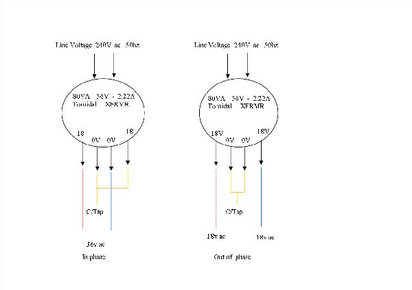
There'll be 4 output wires, and the side of the transformer will show them as White/Orange/Yellow/Blue - 15-0-15-0
In this case you need to use the Orange/Yellow together as the centre tap. (or the White/Blue) but not the Orange/Blue. Does that make sense?
Get it checked by an electrician if you have any doubts at all.
Also keep in mind that that particular transformer won't deliver 1Amp per rail. It's rated at about 800mA in series, so I wouldn't push it past 500mA (per rail)
_________________
What makes a space ours, is what we put there, and what we do there. |
|
|
Back to top
|
|
|
Skrog Productions

Joined: Jan 07, 2009
Posts: 1220
Location: Scottish Borders
Audio files: 159
|
|
|
Back to top
|
|
|
Uncle Krunkus
Moderator
Joined: Jul 11, 2005
Posts: 4761
Location: Sydney, Australia
Audio files: 52
G2 patch files: 1
|
| Posted: Mon Dec 28, 2009 1:42 pm Post subject:
|
|
|
It may have no effect.
But it's not the kinda thing I'd like to try. 
_________________
What makes a space ours, is what we put there, and what we do there. |
|
|
Back to top
|
|
|
Skrog Productions
Joined: Jan 07, 2009
Posts: 1220
Location: Scottish Borders
Audio files: 159
|
| Posted: Sat Jan 02, 2010 3:56 am Post subject:
|
|
|
hey Andy, happy new year.
I'll get back to you on this one, i think i may have inadvertently tried this on the asm supply  , the synth works great but my 15V regs could cook a lovely sunday roast , the synth works great but my 15V regs could cook a lovely sunday roast  , i really will have to pay attention more in future , i really will have to pay attention more in future 
Dave. |
|
|
Back to top
|
|
|
delayed
Joined: Jun 24, 2008
Posts: 130
Location: TN
|
| Posted: Sun Jan 03, 2010 2:56 am Post subject:
|
|
|
Kinda off topic here, but can you take a 15v ac wall wart and make a Y power cable (female to male + male) and be okay? Is there any issues with this?
Basically having two outputs on one wall wart but by making the cable I will not have to cut up the wall wart's cable.
I want to do this for two of Ray's older 1A power boards. I have the +-12VDC power boards running on two different wall warts right now, and would like to only carry around one. |
|
|
Back to top
|
|
|
benuron
Joined: Nov 22, 2009
Posts: 11
Location: Portugal
|
| Posted: Sun Jan 03, 2010 5:16 am Post subject:
|
|
|
This is a good site about transformers
http://sound.westhost.com/xfmr2.htm#8.series-parallel
To connect the output transformer you should connect one start winding of one rail to the end winding of the other.
JoeMorris
The wires you have to connect are the green with the blue or the red with the brown.
See the pdf |
|
|
Back to top
|
|
|
Sound
Joined: Jun 06, 2006
Posts: 842
Audio files: 1
|
| Posted: Sun Jan 03, 2010 6:11 am Post subject:
|
|
|
Joe, The model 62063 that you have chosen is 2X15V, but it should give 2X18 in order to supply if needed +/-15V.
LM317 data says 3V ≤ (VIN − VOUT) ≤ 40V.
So it should be better the model 62064.
Uncle, I think that the secondary should be configured OUT of phase. http://en.wikipedia.org/wiki/Centre_tap
| Quote: | | Volts center tapped (VCT) describes the voltage output of a center tapped transformer. For example: A 24 VCT transformer will measure 24 VAC across the outer two taps (winding as a whole), and 12VAC from each outer tap to the center-tap (half winding). These two 12 VAC supplies are 180 degrees out of phase with each other, thus making it easy to derive positive and negative 12 volt DC power supplies from them. |
According its schematics is red and brown together as a centre tap.
 |
|
|
Back to top
|
|
|
Sound
Joined: Jun 06, 2006
Posts: 842
Audio files: 1
|
| Posted: Sun Jan 03, 2010 6:40 am Post subject:
|
|
|
benuron, when I posted I didnt see your post.
Good link. |
|
|
Back to top
|
|
|
Uncle Krunkus
Moderator
Joined: Jul 11, 2005
Posts: 4761
Location: Sydney, Australia
Audio files: 52
G2 patch files: 1
|
| Posted: Mon Jan 04, 2010 3:10 am Post subject:
|
|
|
Yeah, Sound, schematically that's what I meant. I just thought that would be called in phase. Most transformers have a pic on the side which says something like "15-0/15-0". So for a positive excursion on the primary, the second "0" is -15 with respect to the second 15, so by connecting the middle "0-15" together, you create a +15,0,-15 arrangement. (or something like that)
Anyone with more experience in PSUs is welcome to jump in and "set the record straight" 
_________________
What makes a space ours, is what we put there, and what we do there. |
|
|
Back to top
|
|
|
Sound
Joined: Jun 06, 2006
Posts: 842
Audio files: 1
|
| Posted: Mon Jan 04, 2010 10:20 am Post subject:
|
|
|
Aha, I think that the key is in the link of Benuron, where is explained that is possible connect two secondary in parallel or series and in phase or out of phase. So as I understood the correct name for the configuration needed in bipolar or split supplies is in series and out of phase.
Out of phase assure that the positive and negative rails always receive current, now by one secondary, after by the other depending on the phase. |
|
|
Back to top
|
|
|
benuron
Joined: Nov 22, 2009
Posts: 11
Location: Portugal
|
| Posted: Mon Jan 04, 2010 10:55 am Post subject:
|
|
|
I'm still learning about transformers and psu but this is what I've discovered so far.
When you buy a transformer the manufacturer tell's in a datasheet or in the box of the product where the windings start. This is normaly marked with a point or asterisk. When you know that information it's easy...the start of one winding rail goes to the end of the other winding rail.
I think they must be out of phase to cancel each one and give the 0 volts.
sorry the english  |
|
|
Back to top
|
|
|
Sound
Joined: Jun 06, 2006
Posts: 842
Audio files: 1
|
| Posted: Mon Jan 04, 2010 4:44 pm Post subject:
|
|
|
| Quote: | | I think they must be out of phase to cancel each one and give the 0 volts. |
Ciao Benuron, I think that it is not the reason. Also you can tap the ground in a 'Series/in phase' configuration. I think the reason is that the Series/out of phase configuration has best performance.
As I understand in the Eliot site http://sound.westhost.com/xfmr2.htm#8.series-parallel there are four ways of configure two secondaries:
Series/in phase,
Series/out of phase,
Parallel/in phase and
Parallel/out of phase*
*This last configuration -parallel/out of phase- must be avoided since will destroy the transformer -or in the best case the fuse- Actually is like short a "Series/out of phase" configuration.
For "bipolar supplies" or "split supplies" (+V,-V, 0) we are interested in the series configuration, in order to tap the ground within the two secundaries.
As you can see in the pictures attached the "Series/out of phase" configuration is the one with best performance. I took these pictures measuring after the ring diode, red for the +V output, yellow for the-V output. As you can see it will provide the current more spread to the rails +V and -V. It will make easier the job of the filter capacitor, I think.
Picture 1 corresponds at configuration Series/out of phase.

Picture 2 corresponds at configuration Series/in phase.
 |
|
|
Back to top
|
|
|
benuron
Joined: Nov 22, 2009
Posts: 11
Location: Portugal
|
| Posted: Tue Jan 05, 2010 6:58 pm Post subject:
|
|
|
| Sound wrote: | | Quote: | | I think they must be out of phase to cancel each one and give the 0 volts. |
Ciao Benuron, I think that it is not the reason. Also you can tap the ground in a 'Series/in phase' configuration. I think the reason is that the Series/out of phase configuration has best performance.
|
Hey!Ciao is italian!You wanted to say "Olá" I know... 
Thanks for the explanation. The picture of the osciloscope helped me to understand better. That way the center tap receives voltage/current equally. |
|
|
Back to top
|
|
|
JoeMorris
Joined: Apr 26, 2009
Posts: 161
Location: Brighton
|
| Posted: Wed Jan 06, 2010 2:45 am Post subject:
|
|
|
Thanks for your help people. I built two of these and they work very well.
Joe |
|
|
Back to top
|
|
|
|

 Forum index » DIY Hardware and Software » MusicFromOuterSpace.com designs by Ray Wilson