| Author |
Message |
syntherjack

Joined: Oct 29, 2012
Posts: 21
Location: Poland, Poznan
|
 Posted: Mon Apr 15, 2013 12:39 pm Post subject:
Euro modular power supply project [COMPELETE PCB+SCHEME] Posted: Mon Apr 15, 2013 12:39 pm Post subject:
Euro modular power supply project [COMPELETE PCB+SCHEME]
Subject description: Everything you need to build your reliable modular synthesizer PSU. |
  |
|
Hello,
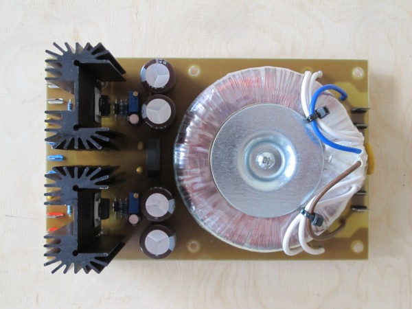
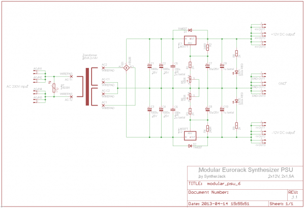
I'm working on my big and fat modular drum synth. As first, I completed PSU - it is designed for euro standard (+/- 12V). Below you can find:
- full schematics,
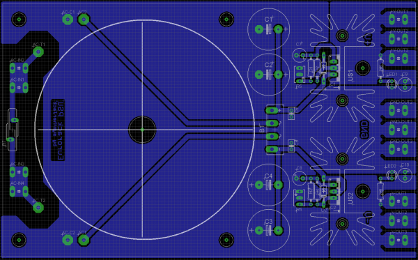
- PCB for easy DIY cloning,
- BOM,
- some pictures.
PSU in based on Doepfers Modular PSU, but has few little upgrades:
- it uses more popular, cheap heat-sinks,
- better quality capacitors,
- protection diodes,
- changed connector spacing for easy operation,
- 2x1,5A output @ 12V (tested).
The PCB is 160x100mm (standard EURO card), one sided.
Total cost cost about 25 euro (when you do PCB on your own).
Happy DIYing!
| Description: |
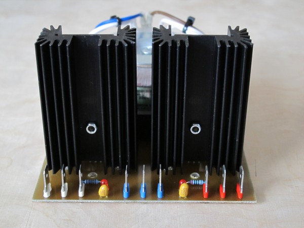
| Completed PSU, output connectors. |
|
| Filesize: |
1.86 MB |
| Viewed: |
239 Time(s) |
| This image has been reduced to fit the page. Click on it to enlarge. |

|
| Description: |
|
| Filesize: |
1.74 MB |
| Viewed: |
272 Time(s) |
| This image has been reduced to fit the page. Click on it to enlarge. |

|
| Description: |
|
| Filesize: |
50.69 KB |
| Viewed: |
433 Time(s) |
| This image has been reduced to fit the page. Click on it to enlarge. |

|
| Description: |
| PSU, bottom PCB side with components. |
|
| Filesize: |
180.83 KB |
| Viewed: |
284 Time(s) |
| This image has been reduced to fit the page. Click on it to enlarge. |

|
| Description: |
| PCB ready to print, parts layout and BOM. |
|

Download (listen) |
| Filename: |
PSU_euro_complete.zip |
| Filesize: |
85.3 KB |
| Downloaded: |
319 Time(s) |
|
|
|
Back to top
|
|
 |
roglok

Joined: Aug 28, 2010
Posts: 202
Location: uptown
|
 Posted: Mon Apr 15, 2013 2:45 pm Post subject: Posted: Mon Apr 15, 2013 2:45 pm Post subject:
|
  |
|
| Wow, looks great. Thanks for posting! |
|
|
Back to top
|
|
 |
Broadwave

Joined: Feb 16, 2007
Posts: 347
Location: Manchester UK
Audio files: 6
|
 Posted: Mon Apr 15, 2013 11:47 pm Post subject: Posted: Mon Apr 15, 2013 11:47 pm Post subject:
|
  |
|
That is a seriously neat design - Thanks, very useful  |
|
|
Back to top
|
|
 |
roglok

Joined: Aug 28, 2010
Posts: 202
Location: uptown
|
 Posted: Mon Apr 15, 2013 11:52 pm Post subject: Posted: Mon Apr 15, 2013 11:52 pm Post subject:
|
  |
|
| One question though: Is there any specific reason for the tantalum caps? Are they just for decoupling the LEDs? I'd like to avoid tantalum because apparently they tend to short circuit in some cases. |
|
|
Back to top
|
|
 |
syntherjack

Joined: Oct 29, 2012
Posts: 21
Location: Poland, Poznan
|
 Posted: Tue Apr 16, 2013 11:46 am Post subject: Posted: Tue Apr 16, 2013 11:46 am Post subject:
|
  |
|
| The main reason to use tantalum caps is LM317 datasheet, they're recommeded. Those caps tend to short circuit when thermal and voltage limits are exceeded. I used 25V, 85C caps, so there shouldn't be a problem. If you have bad experiences with tantalum, you can always 100uF parallel with 100nF. |
|
|
Back to top
|
|
 |
risingson
Joined: Feb 05, 2013
Posts: 1
Location: NYC
|
 Posted: Tue Apr 16, 2013 12:53 pm Post subject: Posted: Tue Apr 16, 2013 12:53 pm Post subject:
|
  |
|
| Thanks for this! Would you consider open-sourcing schematics and layout files? It would be easier for me to get a few fabricated then to etch myself. |
|
|
Back to top
|
|
 |
01012k7

Joined: Aug 31, 2013
Posts: 25
Location: England
|
|
|
Back to top
|
|
 |
syntherjack

Joined: Oct 29, 2012
Posts: 21
Location: Poland, Poznan
|
 Posted: Sun Sep 01, 2013 2:50 am Post subject: Posted: Sun Sep 01, 2013 2:50 am Post subject:
|
  |
|
Nice job!
I hope it will work fine for long years! |
|
|
Back to top
|
|
 |
01012k7

Joined: Aug 31, 2013
Posts: 25
Location: England
|
|
|
Back to top
|
|
 |
|

