| Author |
Message |
MapacheRaper

Joined: Feb 15, 2018
Posts: 166
Location: Spain
|
|
|
Back to top
|
|
 |
LFLab
Joined: Dec 17, 2009
Posts: 497
Location: Rosmalen, Netherlands
|
 Posted: Mon Jun 18, 2018 6:52 am Post subject: Posted: Mon Jun 18, 2018 6:52 am Post subject:
|
  |
|
| Not being familiar with that regulator, does that have floating or isolated outputs? If so, that yeah that will work. |
|
|
Back to top
|
|
|
MapacheRaper
Joined: Feb 15, 2018
Posts: 166
Location: Spain
|
| Posted: Mon Jun 18, 2018 11:44 am Post subject:
|
|
|
Not really sure what you mean. The negative input and output are directly connected, if it´s what you mean. The regulation happens in the positive rail.
Does it means it´s floating type?. Should this be a problem? |
|
|
Back to top
|
|
|
blue hell
Site Admin

Joined: Apr 03, 2004
Posts: 24488
Location: The Netherlands, Enschede
Audio files: 298
G2 patch files: 320
|
| Posted: Mon Jun 18, 2018 12:51 pm Post subject:
|
|
|
| MapacheRaper wrote: | | [...]The negative input and output are directly connected[...] |
This means that with your circuit proposal you create a short circuit (just follow the wires ... ), so this will not work unfortunately.
_________________
Jan
also .. could someone please turn down the thermostat a bit.
 |
|
|
Back to top
|
|
|
MapacheRaper
Joined: Feb 15, 2018
Posts: 166
Location: Spain
|
| Posted: Mon Jun 18, 2018 4:54 pm Post subject:
|
|
|
Damn!
So it was too good to be true. Now Im guessing if you can put some diodes (not sure if before the output or after) to isolate the circuit.
Any ideas on how to isolate it and render it usable would be most welcome.
Thanks for pointing at the error!  |
|
|
Back to top
|
|
|
AlanP
Joined: Mar 11, 2014
Posts: 746
Location: New Zealand
Audio files: 41
|
| Posted: Mon Jun 18, 2018 5:38 pm Post subject:
|
|
|
TANSTAAFL, I guess.
You could try using two regulators, and TWO dc power supplies.
But by then, you may as well just use two decent 12VDC wallwart power supplies, some filtering, and not bother with these modules. |
|
|
Back to top
|
|
|
blue hell
Site Admin
Joined: Apr 03, 2004
Posts: 24488
Location: The Netherlands, Enschede
Audio files: 298
G2 patch files: 320
|
|
|
Back to top
|
|
|
MapacheRaper
Joined: Feb 15, 2018
Posts: 166
Location: Spain
|
| Posted: Tue Jun 19, 2018 9:51 pm Post subject:
|
|
|
Yeah, I have spent some good hours trying to find some loophole to feed it from only one DC source, but seems like it´s contranatura. Diodes don´t work and there seems to not exist a negative counterparty to the LM2575 that insulates the negative rail.
In fact I have a centertapped transformer coming home, that I will adjust with LM317 and LM337, the typical suspects. This is for my main and first Euro setup and I want it as clean as possible.
The idea of this thread was to recycle a laptop brickwall- that all people has some spare- and use the LM2595 chinese modules to get the most cheap possible power supply. (And playing with the filtering stage to tame decently)
In fact after crunching some offers in ebay, is way more cheap to buy 2x 15v 2A brickwalls than a CT transformer, but this is more elegant, for sure.
Thank you so much for taking the time to help and to solve the puzzle  |
|
|
Back to top
|
|
|
LFLab
Joined: Dec 17, 2009
Posts: 497
Location: Rosmalen, Netherlands
|
| Posted: Wed Jun 20, 2018 6:12 am Post subject:
|
|
|
| The alternative is a DC/DC converter, those can be used with a laptop PSU, if you choose the right one. They usually also have isolated outputs (but not all!) and can be had with two pairs of outputs. Think about 40 euros in a 30watt version. |
|
|
Back to top
|
|
|
JovianPyx

Joined: Nov 20, 2007
Posts: 1988
Location: West Red Spot, Jupiter
Audio files: 224
|
| Posted: Wed Jun 20, 2018 7:37 am Post subject:
|
|
|
The above schematic ( http://www.circuitstoday.com/wp-content/uploads/2011/03/dual-supply-for-tone-control-circuit.png ) works if a dot is placed on the negative connection of C2. That is, if the convention of dots for connections and no dots for crossover is maintained. This schematic is rather weird since there are also jump over curves used.
Also, one of the simplest dual supplies is made with a non-center tapped AC wallwart or transformer with two half wave rectifiers. I've never had any trouble with this design, but it does require larger filter caps than for full wave.
_________________
FPGA, dsPIC and Fatman Synth Stuff
Time flies like a banana.
Fruit flies when you're having fun.
BTW, Do these genes make my ass look fat?
corruptio optimi pessima
|
|
|
Back to top
|
|
|
LFLab
Joined: Dec 17, 2009
Posts: 497
Location: Rosmalen, Netherlands
|
| Posted: Fri Jun 22, 2018 2:39 am Post subject:
|
|
|
| JovianPyx wrote: |
Also, one of the simplest dual supplies is made with a non-center tapped AC wallwart or transformer with two half wave rectifiers. I've never had any trouble with this design, but it does require larger filter caps than for full wave. |
This!
Used it a lot, see the late great Ray Wilsons article:
Wall wart PSU on MFOS |
|
|
Back to top
|
|
|
MapacheRaper
Joined: Feb 15, 2018
Posts: 166
Location: Spain
|
| Posted: Fri Jun 22, 2018 4:53 pm Post subject:
|
|
|
I read somewhere in muffwligger´s that the simple AC current produces more ripple, noise and is less eficient. Tons of pages of obsesivecompulsiviness minutia and details about the topic. So I thoght, fuck, lets go the "pro" route.
After that I have see tons of people recomending and happy with the single AC regulators and for sure will be my next power supply.
That way I can even switch between supplies and ear it by myself.
By the way, today I have received the center tapped transformer. 15/-15V, 1 A in every rail. The thing is MASSIVE. I was expection something more reasonably sized and lightweight. So big that probably doesn´t enter in the eurorack case, or left very little depth for some number of modules
I don´t recomment it for starters at all. Whatever, lets see how it works! |
|
|
Back to top
|
|
|
blue hell
Site Admin
Joined: Apr 03, 2004
Posts: 24488
Location: The Netherlands, Enschede
Audio files: 298
G2 patch files: 320
|
| Posted: Fri Jun 22, 2018 5:35 pm Post subject:
|
|
|
| MapacheRaper wrote: | | [...]MASSIVE[...] |

and then .. it will get hot too .. not the transformer .. but the regulators.
Going to derail the thread a little now 
I think that given the state of nowadays switchers analog synth builders should move on to switching power supplies .. they are efficient and clean .. commercial builds have had them for over 20 years now .. the times of 50 kHz switchers causing audio interference has long passed .. it is all 1 MHz stuff now (20 * 50  ). ).
Anyway . .that is why I really felt bad to have to say that the simple approach this thread started with would not work. But as pointed out in the messages above there is no need to fall back to the classic PSU ideas .. as you can actually buy floating switchers not having the issue, or dual switching supplies.
Just do it .. it will save the planet too  |
|
|
Back to top
|
|
|
AlanP
Joined: Mar 11, 2014
Posts: 746
Location: New Zealand
Audio files: 41
|
| Posted: Fri Jun 22, 2018 11:19 pm Post subject:
|
|
|
| The Meanwell RT-65B is popular on MW -- you need a load on the 5V rail, however, so a power resistor for that may be needed. |
|
|
Back to top
|
|
|
gabbagabi

Joined: Nov 29, 2008
Posts: 652
Location: Berlin by n8
Audio files: 23
|
| Posted: Sat Jun 23, 2018 12:17 am Post subject:
|
|
|
Does anyone has experience with computer power supplys ?
They have a lot of power, they are ready made, no-one use them,
is there a why? |
|
|
Back to top
|
|
|
AlanP
Joined: Mar 11, 2014
Posts: 746
Location: New Zealand
Audio files: 41
|
| Posted: Sat Jun 23, 2018 12:20 am Post subject:
|
|
|
Computer PSU's are not known for low ripple current, they are known for a lot of power on tap.
Actually... what is the minimum load for a typical computer PSU? I know that minimum load is a factor for switching PSU's  |
|
|
Back to top
|
|
|
gabbagabi
Joined: Nov 29, 2008
Posts: 652
Location: Berlin by n8
Audio files: 23
|
| Posted: Sat Jun 23, 2018 8:46 am Post subject:
|
|
|
in all those "instrutables" they talk about 10Ohm 5Watt or better 10Watt-Resistor at the 5V Output.
that should be 0,5Amp.
edit: i had a little read in the hardest elektonik form of the world (of course it is german) "microcontroller.net" they where mostly not so happy about them,
because of bad behaveiour when load changes and that u have like 20A on the point where one had produced a short circuit.
the one happy guy is using a 21Watt/6V car lightbulb on the 5V rail as a load, so he can take always a good load out of the 12V rail, there seems to be a dependence between the 5V and 12V rail.
and we sdiy-honks are not producing a lot of load changes
stays the argument with the shortcircuit |
|
|
Back to top
|
|
|
MapacheRaper
Joined: Feb 15, 2018
Posts: 166
Location: Spain
|
| Posted: Sat Jun 23, 2018 5:00 pm Post subject:
|
|
|
| Blue Hell wrote: | | MapacheRaper wrote: | | [...]MASSIVE[...] |
and then .. it will get hot too .. not the transformer .. but the regulators.
Going to derail the thread a little now
I think that given the state of nowadays switchers analog synth builders should move on to switching power supplies .. they are efficient and clean .. commercial builds have had them for over 20 years now .. the times of 50 kHz switchers causing audio interference has long passed .. it is all 1 MHz stuff now (20 * 50 ).
Anyway . .that is why I really felt bad to have to say that the simple approach this thread started with would not work. But as pointed out in the messages above there is no need to fall back to the classic PSU ideas .. as you can actually buy floating switchers not having the issue, or dual switching supplies.
Just do it .. it will save the planet too |
That´s a reality bath and a lot of wise tips.
I was expecting the regulators to get hot on heavy load... will it get hot with light load too? (facepalm). It will come handy in winter time, I guess...
Next time I will start reading here. In fact Im totally addicted to this site. Thanks Blue Hell! |
|
|
Back to top
|
|
|
blue hell
Site Admin
Joined: Apr 03, 2004
Posts: 24488
Location: The Netherlands, Enschede
Audio files: 298
G2 patch files: 320
|
| Posted: Sat Jun 23, 2018 5:12 pm Post subject:
|
|
|
| MapacheRaper wrote: | | will it get hot with light load too? |
No .. the heat comes from the voltage drop over it multiplied by the current going trough .. so with the current going down so does the heat. At zero load the efficiency will be great .. then going worse when the current goes up.
_________________
Jan
also .. could someone please turn down the thermostat a bit.
|
|
|
Back to top
|
|
|
MapacheRaper
Joined: Feb 15, 2018
Posts: 166
Location: Spain
|
| Posted: Sun Jun 24, 2018 3:01 am Post subject:
|
|
|
| Blue Hell wrote: | | MapacheRaper wrote: | | will it get hot with light load too? |
No .. the heat comes from the voltage drop over it multiplied by the current going trough .. so with the current going down so does the heat. At zero load the efficiency will be great .. then going worse when the current goes up. |
That totally makes sense. Thanks! |
|
|
Back to top
|
|
|
MapacheRaper
Joined: Feb 15, 2018
Posts: 166
Location: Spain
|
| Posted: Thu Feb 21, 2019 2:32 pm Post subject:
|
|
|
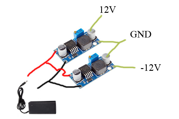
So it seems somebody has build a design like this and its working... I don´t understand how, it should be shorting the power brick...
Magic? Magic smoke? Tons of magic smoke??
http://nozoid.com/diy-eurorack-power-supply/ |
|
|
Back to top
|
|
|
PHOBoS
Joined: Jan 14, 2010
Posts: 5868
Location: Moon Base
Audio files: 709
|
|
|
Back to top
|
|
|
MapacheRaper
Joined: Feb 15, 2018
Posts: 166
Location: Spain
|
| Posted: Thu Feb 21, 2019 3:22 pm Post subject:
|
|
|
| Yeah, probably nozoid used a digital LFO that was only feeding from the +12 and GND, so it worked. It´s the only logical explanation |
|
|
Back to top
|
|
|
blue hell
Site Admin
Joined: Apr 03, 2004
Posts: 24488
Location: The Netherlands, Enschede
Audio files: 298
G2 patch files: 320
|
| Posted: Thu Feb 21, 2019 3:40 pm Post subject:
|
|
|
Hah, of course .. just redraw it a bit .. and it will make sense .. the negative regulator regulates ground to be 12V above -12V .. and the positive one has GND as a reference to regulate its output to 12V above that.
Actually .. I once had a PSU built like that .. with two positive regulators to make a dual supply ...and had forgotten about it..
_________________
Jan
also .. could someone please turn down the thermostat a bit.
|
|
|
Back to top
|
|
|
elektrouwe
Joined: May 27, 2012
Posts: 146
Location: Germany
|
| Posted: Thu Feb 21, 2019 4:02 pm Post subject:
|
|
|
sorry, but I see many false statements in this thread and the nice looking
noizoid page is full of "alternative facts"
I tried to discuss it here ( with no response from the author):
https://www.muffwiggler.com/forum/topic-212318.html |
|
|
Back to top
|
|
|
|

 Forum index » DIY Hardware and Software