| Author |
Message |
jhaible
Joined: May 25, 2007
Posts: 2014
Location: Germany
Audio files: 24
|
 Posted: Tue Sep 01, 2009 2:07 am Post subject: Posted: Tue Sep 01, 2009 2:07 am Post subject:
|
  |
|
| Funky40 wrote: | I went thru calibration inclouding step 5
At step 5 i got 3V out for the comp output. Trimmer is in endposition.
Not measured any Frequenzys, so i could have been aside.
( The calibratioon was also more meant to to be able to see if the module works. )
so far the 3V cmp-out seem to be the only Problem. |
If everything else works, I wouldn't think much about the levels being a few dBs off. - If you want to, you can change the resistor value that is connected in series with the trimpot. (These OTAs may have higher gain tolerances than I had expected.) - But really, if it sounds ok, I wouldn't spend much thought about the level.
JH.
_________________
"I tell you the truth, if anyone says to this mountain, 'Go, throw yourself into the sea,' and does not doubt in his heart but believes that what he says will happen, it will be done for him. Therefore I tell you, whatever you ask for in prayer, believe that you have received it, and it will be yours." (Mk 11,23f) |
|
|
Back to top
|
|
 |
Funky40
Joined: Sep 24, 2005
Posts: 875
Location: Swiss
Audio files: 1
G2 patch files: 5
|
| Posted: Tue Sep 01, 2009 11:21 am Post subject:
|
|
|
I could patch the FS-1A today for around 40 minutes.
Just tried with a Drumpatch, 808 BD. ---> Frequency shifters are bad things hehe.
The Module is not finished, also have to change some things, but electronics work as it seems to me. Must test with some speaking thru it.
I'll report back.
#2 is nearly ready for final wiring too
ahhh, if changing the Resistor for comp out gain : higher or lower ?
what i can say is: it looks as i also have to add a 50K Resistor into the Feedback path.
thanks so far Jürgen ! |
|
|
Back to top
|
|
|
Funky40
Joined: Sep 24, 2005
Posts: 875
Location: Swiss
Audio files: 1
G2 patch files: 5
|
| Posted: Sat Sep 12, 2009 6:16 am Post subject:
|
|
|
Thank you very much for this wonderful Module Jürgen !
I patched a little bit, mostly noises, and tested my FS-1A on a Recoring with some voice. Seem to work fine.
I'm very proud that i have built successfully the FS-1A i must say .
...and it's a Noise montser   I mean when patching nonsense/Noise and adding Feedback. Results can be astonishing pleasing. I mean when patching nonsense/Noise and adding Feedback. Results can be astonishing pleasing.
( sorry, no possibility to record anything )
In the meantime i built a second one.
That one has a oscillation somewhere, and calibrationstep 1 is not working.
I thought it must be the wiring, but after a first checking this looks good to me.
Must check again and post my questions directly when looking.
Need some measurmentpoints to compare my two Modules
Jürgen if you have some hints by now, i'm glad to hear them |
|
|
Back to top
|
|
|
jhaible
Joined: May 25, 2007
Posts: 2014
Location: Germany
Audio files: 24
|
| Posted: Sat Sep 12, 2009 6:57 am Post subject:
|
|
|
| Funky40 wrote: | Thank you very much for this wonderful Module Jürgen !
I patched a little bit, mostly noises, and tested my FS-1A on a Recoring with some voice. Seem to work fine.
I'm very proud that i have built successfully the FS-1A i must say .
...and it's a Noise montser I mean when patching nonsense/Noise and adding Feedback. Results can be astonishing pleasing.
( sorry, no possibility to record anything )
In the meantime i built a second one.
That one has a oscillation somewhere, and calibrationstep 1 is not working.
I thought it must be the wiring, but after a first checking this looks good to me.
Must check again and post my questions directly when looking.
Need some measurmentpoints to compare my two Modules
Jürgen if you have some hints by now, i'm glad to hear them |
With one already running, and the two side by side, you have the best reference object for comparison!
JH.
_________________
"I tell you the truth, if anyone says to this mountain, 'Go, throw yourself into the sea,' and does not doubt in his heart but believes that what he says will happen, it will be done for him. Therefore I tell you, whatever you ask for in prayer, believe that you have received it, and it will be yours." (Mk 11,23f) |
|
|
Back to top
|
|
|
Funky40
Joined: Sep 24, 2005
Posts: 875
Location: Swiss
Audio files: 1
G2 patch files: 5
|
|
|
Back to top
|
|
|
vtl5c3
Joined: Sep 08, 2006
Posts: 425
Location: PDX
Audio files: 13
|
| Posted: Thu Sep 17, 2009 6:49 pm Post subject:
|
|
|
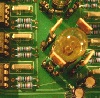
| Wow. That's a nice looking panel (for an awesome circuit)! |
|
|
Back to top
|
|
|
Funky40
Joined: Sep 24, 2005
Posts: 875
Location: Swiss
Audio files: 1
G2 patch files: 5
|
| Posted: Sat Sep 19, 2009 10:32 pm Post subject:
|
|
|
Thanks VTL.
just patched 6 Hours nonstop with the FS-1A, not counting the hours the day.....
---------> build that FS-1A with a Feedback output i say ( or SUM and DIFF outputs ), or both.
I'm VERY impressed with the results from first patchings within the feedbackloop. IMO the FB insert is a must have ( go for a addon module if your FS-1A is allready built )
tested so far: LPG, CGS Grinder, 512stage BBD ( Doepfer) and all together.Grinder and BBD have muteswitch.
it's just WOW, and it "can" be VEEEERY musical. Easyer and better than FB without additional patchings.
..........speaking from patching crap/nonsense/Noise..............but the groovy one that sounds........  never heard more pleasing noises. never heard more pleasing noises. |
|
|
Back to top
|
|
|
Funky40
Joined: Sep 24, 2005
Posts: 875
Location: Swiss
Audio files: 1
G2 patch files: 5
|
| Posted: Mon Sep 21, 2009 3:42 pm Post subject:
|
|
|
Wow, debugged my JH FS-1A #2.
I thought it must be the wiring, and i double checked all the connections going to the Board,
but guess not checked the connections between the Boards.
the interconnections of SigCos and Input where exchanged  , ,
don't know, my Eyes could not see it........it was now a coinsidence while surching for the fault. Debugging was then very easy
Just finished calibration. gonna recalibrate both units later again.
now, what to take out to get space ?
wow, i'm happy.  Each JH FS-1A was near to 400.-CHF / 350.-$ Each JH FS-1A was near to 400.-CHF / 350.-$
( with B-Funk partkits and supercheapo faceplate, but good apem switches and good jacks ) |
|
|
Back to top
|
|
|
zthee

Joined: Feb 20, 2008
Posts: 414
Location: Stockholm
|
|
|
Back to top
|
|
|
sduck

Joined: Dec 16, 2007
Posts: 459
Location: Nashville
Audio files: 5
|
| Posted: Wed Oct 14, 2009 7:19 pm Post subject:
|
|
|
That's great! I loved the grinning zthee at the end.
That carrier bleed is pretty extreme - maybe just some recalibration will cure that? Probably Jurgen will know... |
|
|
Back to top
|
|
|
zthee
Joined: Feb 20, 2008
Posts: 414
Location: Stockholm
|
| Posted: Wed Oct 14, 2009 11:46 pm Post subject:
|
|
|
Thanks! It not me grinning though, but my friend who just helped me calibrate it
I always mix up carrier and signal.. The internal VCO is not hear, but it seems like the signal coming into the FS1A is not entirely processed. There seems to be no way to trim it away?
_________________
http://www.thehumancomparator.net/ |
|
|
Back to top
|
|
|
/mr
Joined: Aug 05, 2007
Posts: 223
Location: Elektron City, Sweden
Audio files: 1
|
| Posted: Fri Oct 16, 2009 5:19 pm Post subject:
|
|
|
Happy to see that you have a good time...
| zthee wrote: | | I always mix up carrier and signal.. The internal VCO is not hear, but it seems like the signal coming into the FS1A is not entirely processed. There seems to be no way to trim it away? |
This is definitely not what it should sound like, that whistle shouldn't be there. I'm not sure exactly what all the trimpots do, though...
One thing that just struck me - if you'd have a DC component in your input signal by accident, wouldn't it end up this way? Shifted up to a whistling sinewave? Just a thought in the night.  |
|
|
Back to top
|
|
|
Funky40
Joined: Sep 24, 2005
Posts: 875
Location: Swiss
Audio files: 1
G2 patch files: 5
|
| Posted: Wed Dec 02, 2009 4:06 pm Post subject:
|
|
|
How to patch the FS-1A that it tracks 1V/oct ?
I mean, whats the basic setting ? |
|
|
Back to top
|
|
|
vtl5c3
Joined: Sep 08, 2006
Posts: 425
Location: PDX
Audio files: 13
|
| Posted: Sat Dec 05, 2009 6:21 pm Post subject:
Mic Input Wiring Q |
|
|
I'm finally getting around to wiring up my first FS. I'm a little confused by the diagram for the Mic Input. Is the shield connected to ground on the TRS Jack and the GND pad on the Mic input? Is this a case where you want the coax shield connected on both ends?
R.
[/i] |
|
|
Back to top
|
|
|
jhaible
Joined: May 25, 2007
Posts: 2014
Location: Germany
Audio files: 24
|
| Posted: Sun Dec 06, 2009 2:18 am Post subject:
Re: Mic Input Wiring Q |
|
|
| vtl5c3 wrote: | I'm finally getting around to wiring up my first FS. I'm a little confused by the diagram for the Mic Input. Is the shield connected to ground on the TRS Jack and the GND pad on the Mic input? Is this a case where you want the coax shield connected on both ends?
R.
[/i] |
Grounding is a difficult thing, and depends on many parameters of your whole system. And there's different philosophies about right grounding, also. 
My drawing just gives you a hint how things would be connected with insulated jacks, so that shield would be the only GND connection. For other conditions, other grounding concepts apply. So, take my drawings just as a hint, and adapt it to your system and its grounding scheme.
JH.
_________________
"I tell you the truth, if anyone says to this mountain, 'Go, throw yourself into the sea,' and does not doubt in his heart but believes that what he says will happen, it will be done for him. Therefore I tell you, whatever you ask for in prayer, believe that you have received it, and it will be yours." (Mk 11,23f) |
|
|
Back to top
|
|
|
paulshillito
Joined: Mar 15, 2010
Posts: 5
Location: UK
|
Posted: Mon May 10, 2010 7:24 am Post subject:
Subject description: distorted sumout in FS1a |
|
|
I have recently built an FS1a but it rapidly developed a strange fault that I cant seem to get to the bottom of.
After the build and setup i noticed that the UP output out was very loud and distorted. I used a sine as an input and on investigation I found the SumOut was just a squarewave output switching from +/- 13.5V all the time instead following the diffOut which goes from a few hundred Mv up +/-12V when it starts to clip depending upon the input. I traced it back to the pin 12 output of U17B LM13600. Only when the input is at a very low level a few hundred mV does the SumOut have a positive sine top and a flat -2V bottom as is was almost half wave rectified, any more and snaps back to a full output squarewave.
I checked the inputs on pin 14 and 15 and these are about +15mV to -20mV (there a little bit of negative DC offset) and clearly shows the two outputs from the 1496's fine and out of phase. There is -12V in to pin 16 and 1 from the compander section and that is working all OK. If someone put a 5V 1KHz sine wave into the input of the FS1a, what would you expect to see on pins 14 and 15 of the U17B LM13600?, that should go a long way to seeing if the problem is with 13600 or before then in the 1496's.
The other half of the LM13600 for DiffOut is working fine, so I have no problems with the DOWN output. The whole thing had been working OK for about 30 minutes or more after which the problem occured, which pretty much rules out and wrong value resistors as it would not have worked at all with that issue.
To see if was the output of the LM13600 or the op-amp that was causing the problem I cut the track that joins them and still had +/-13.5V on the output of the LM13600. So I replaced the LM13600, everything worked OK and the output was normal level again. I ran thru the calibration again then the problem reoccured after about 30 minutes, exactly the same problem of the LM13600 acting like a switching comparitor rather than an amplifier. I have checked all the components, joints and signals in and out, I even replaced the LM13600 with a third one but this time it did not fix the problem. I have adjusted R127 and R133 but to no avail. The oscillator output is balanced and all the other calibrations are as they should be.
I have come to a dead end as to why this half LM13600 would be do this hard switching instead of amplifying. THe only thing I can think of is the phase of the inputs but that would be determined by the design which obviously works. Do you have any idea as to why this maybe occuring??
Regards
Paul
Last edited by paulshillito on Mon May 10, 2010 7:42 am; edited 1 time in total |
|
|
Back to top
|
|
|
jhaible
Joined: May 25, 2007
Posts: 2014
Location: Germany
Audio files: 24
|
| Posted: Mon May 10, 2010 7:38 am Post subject:
|
|
|
Hi Paul,
that's strange indeed, and I wouldn't expect the 13600 to be the culprit.
Maybe there is a bad solder joint that goes from connected to unconnected after some time. As you level dramatically increases, I suspect the bad solder joint is on a shunt resistor (OTA input divider maybe), or on a feedback resistor of an opamp. Just a guess, of course.
JH.
_________________
"I tell you the truth, if anyone says to this mountain, 'Go, throw yourself into the sea,' and does not doubt in his heart but believes that what he says will happen, it will be done for him. Therefore I tell you, whatever you ask for in prayer, believe that you have received it, and it will be yours." (Mk 11,23f) |
|
|
Back to top
|
|
|
paulshillito
Joined: Mar 15, 2010
Posts: 5
Location: UK
|
| Posted: Mon May 10, 2010 8:00 am Post subject:
|
|
|
Thanks Jurgen,
If there was a faulty joint on one of the 470R shunts then i should be getting a much larger input on either of the 13600 inputs that was affected but they are within a mV of each other whilst the output of the 13600 is clamping hard on before it gets to the opamp, this is most strange.
Is there anything in the phase difference to the inputs that would make the OTA work like a comparitor?, I cant see it but...
Paul |
|
|
Back to top
|
|
|
paulshillito
Joined: Mar 15, 2010
Posts: 5
Location: UK
|
| Posted: Thu May 13, 2010 4:29 pm Post subject:
|
|
|
| Problem Found !!! at last and with the aid of some freezer spray and a hair dryer it turned out to be a dry joint on a shunt resistor, just as you suggested, you D'man |
|
|
Back to top
|
|
|
jhaible
Joined: May 25, 2007
Posts: 2014
Location: Germany
Audio files: 24
|
| Posted: Thu May 13, 2010 9:07 pm Post subject:
|
|
|
| paulshillito wrote: | | Problem Found !!! at last and with the aid of some freezer spray and a hair dryer it turned out to be a dry joint on a shunt resistor, just as you suggested, you D'man |
Glad it worked!
I just hope they find the reason for a very *similar* intermittent problem on the electronics of my Citroen C4, which is at the repair shop right now ...
JH. (Seen a lot on bicyle lately)
_________________
"I tell you the truth, if anyone says to this mountain, 'Go, throw yourself into the sea,' and does not doubt in his heart but believes that what he says will happen, it will be done for him. Therefore I tell you, whatever you ask for in prayer, believe that you have received it, and it will be yours." (Mk 11,23f) |
|
|
Back to top
|
|
|
vtl5c3
Joined: Sep 08, 2006
Posts: 425
Location: PDX
Audio files: 13
|
Posted: Sat Aug 14, 2010 11:33 am Post subject:
 Finally completed! Finally completed! |
|
|
I've pretty much completed my first JH FS. Today I did a simple test run to see what it could do to a drum machine. Here's the (raw and unedited) result:
http://soundcloud.com/jetfinger/haible-fs-and-ry30
I had no idea that a frequency shifter could provide so much tonal variety!!! Thank you Juergen, for making such a rare module available to us! |
|
|
Back to top
|
|
|
Serenadi
Joined: Jul 03, 2007
Posts: 89
Location: Germany
|
| Posted: Sat Aug 21, 2010 5:11 am Post subject:
Lights ! - Lights ? |
|
|
I just made a mystic experience.
Last days, I built my two sets of pcbs of the fs1a.
I always test pcbs on my workbench before making any wiring or housing. So I did with these four fs1a pcbs. I only wired the "range" pot of the mainboard (exponential control) to make the first adjustments. Everythings works fine with the first one (adjustment steps 1-4).
Then i came to the second one. I discerned a strange behavior of the range pot. It worked like an acceleration pot of the frequency of the QVCO. Turned to the right a bit, the frequency started to increase, even when I stopped the pot movement. The frequency increased until its highest value (ca 25kHz). The same when I turned the pot to the left (only a bit), the frequency decreased to zero. So, adjusting a certain frequency was like turning in the direction of the wanted value a little bit, then stopping the increasing by turning the pot to the opposite direction a bit. It feels like a rubber band.
After a while running, the frequency decreased to zero without any action from me.
Also connecting the "direction" led, the frequency decreased to zero immediately.
Having two identical pcbs, one running perfectly, I thought it would be easy to compare and to find the error.
Wrong thoughts!
I spent several hours searching for this fault, replacing several components, couldn't find anything.
I have to say, I worked mostly at night, with two lights (normal 60W bulbs) over my workbench.
The third evening it wasn't that late, it is summer, I worked without the lights. While experimenting and searching for the fault, it got darker outside, so I switched on the lights.
The frequency of the VCO decreased to zero immediately !!!
I couldn't believe my eyes.
You know, there isn't any opto-electronic component on that board.
I tested again and again - switching on the lights, the VCO stopped working, switching of the lights, the VCO starts running. The rubber - behavior of the range pot was still there, of course. I moved a little black piece of foam over the pcb to find the place, it was light dependent.
To make it not that long:
The diodes D1 and D2 (after U3) were those two behaving improperly.
They are housed in glass, but I never heard of light dependance of 1N4148, but you can notice it also when measuring the forward voltage of a glassy diode.
I replaced them with other 1N4148, even with 1N914 (also glass housing), but no improvement. By the way, I noticed the same light dependance behavior at the first pcb also, but not so dramatically. It changes the frequency just 20% when switching on the lights.
I finally replaced the two diodes with 1N4001, the only ones I had with black plastic housing.
And voila: Everything works fine now, even the rubber band behavior of the range pot has nearly disappeared.
But not completely, in the upper range (ca. 5 kHz), the frequency still tends to rise - and this is on both pcbs.
So, the circuit seems to be very sensitive to very little changes in voltage at this point (U3). I really would like to read about your experiences, or a little comment of Jürgen. Thanks.
Cheers,
Bernd |
|
|
Back to top
|
|
|
jhaible
Joined: May 25, 2007
Posts: 2014
Location: Germany
Audio files: 24
|
| Posted: Sat Aug 21, 2010 7:27 am Post subject:
|
|
|
Interesting.
So, is an ordinary enclosure (for the whole Device) good enough to prevent this effect?
Otherwise, switching to diodes in plastic package, should be an easy, and unexpected improovement.
Did anybody else notice something like that?
JH.
_________________
"I tell you the truth, if anyone says to this mountain, 'Go, throw yourself into the sea,' and does not doubt in his heart but believes that what he says will happen, it will be done for him. Therefore I tell you, whatever you ask for in prayer, believe that you have received it, and it will be yours." (Mk 11,23f) |
|
|
Back to top
|
|
|
Serenadi
Joined: Jul 03, 2007
Posts: 89
Location: Germany
|
| Posted: Mon Aug 23, 2010 1:53 pm Post subject:
|
|
|
| jhaible wrote: | | So, is an ordinary enclosure (for the whole Device) good enough to prevent this effect? |
Maybe. If you close the shutters it will be better for sure.
No one to confirm? Or even confirm the opposite?
Ok, you folks think, this guy from Germany is completely stupid.
I further played around with my two mainboards, one stuffed with 1N4148, the other with 1N4001. Nice to compare.
All I told above occurs when linear control is set to zero. I wrote, I had only the range pot connected. This means, linear control is nearly zero. Even better to retrace when setting the middle pin of the pots "manual" and "fine" to ground (with both pots left in the middle position of course).
In this case, and with the range pot set to a very low value, the QVCO frequency is nearly zero too, but it doesn't stop completely. I think this is because of slightly tolerances in the circuit.
If you now increase the range pot to get higher frequencies, this range pot gets the described rubber band feeling and the light dependance of the two 1N4148 affects the circuit in a strong way. With 1N4001 the circuit is much more stable and - of course - light independent.
But I think I understand the way of control, the difference between linear and expo control of the frequency shifter much better now. I think, the described situation (with linear control set to zero and range turned to a high value) isn't a useful setting for a frequency shifter, maybe good for strange effects.
Until NOW, I only payed attention to the QVCO. Next experience will be, to set it up completely and listen to its frequency shifting.
Anyway, somebody here made the outputs of the QVCO available at the faceplate - I *think* this is a good idea.
Toodle-oo
Bernd |
|
|
Back to top
|
|
|
jhaible
Joined: May 25, 2007
Posts: 2014
Location: Germany
Audio files: 24
|
| Posted: Mon Aug 23, 2010 2:24 pm Post subject:
|
|
|
| Serenadi wrote: |
All I told above occurs when linear control is set to zero. I wrote, I had only the range pot connected. This means, linear control is nearly zero. |
That explains a lot. As with every division by (almost) zero, the tinyest side effect will gain unexpected influence.
So the effect you describe won't really be important for "reasonable" settings, but will still shed some light (pun intended) on not-so-ordinary behaviour of components. - Yes, silicon pn junctions *are* sensitive to photons.
JH.
_________________
"I tell you the truth, if anyone says to this mountain, 'Go, throw yourself into the sea,' and does not doubt in his heart but believes that what he says will happen, it will be done for him. Therefore I tell you, whatever you ask for in prayer, believe that you have received it, and it will be yours." (Mk 11,23f) |
|
|
Back to top
|
|
|
|

 Forum index » DIY Hardware and Software » Jürgen Haible designs

