| Front Page | Radio | Media | Forum | Wiki | Links |

and electronic music
|
|
Dedicated to
experimental electro-acoustic and electronic music |
|
|
|
 Forum index » DIY Hardware and Software » MusicFromOuterSpace.com designs by Ray Wilson Forum index » DIY Hardware and Software » MusicFromOuterSpace.com designs by Ray Wilson |
|
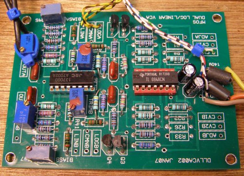
Improving the MFOS Dual Log/Linear VCA
|
 
|
Moderators: dnny, Uncle Krunkus, v-un-v
Page 1 of 1 [3 Posts] |
View unread posts View new posts in the last week Mark the topic unread :: View previous topic :: View next topic |
| Author | Message | |||||||||||||||||
|---|---|---|---|---|---|---|---|---|---|---|---|---|---|---|---|---|---|---|
The Peasant
 Joined: Nov 13, 2009 Posts: 114 Location: Sunny Alberta Audio files: 1 |
|
|||||||||||||||||
|
|
||||||||||||||||||
|
The Peasant
Joined: Nov 13, 2009 Posts: 114 Location: Sunny Alberta Audio files: 1 |
|
|||||||||||||||||
|
|
||||||||||||||||||
PHOBoS
 Joined: Jan 14, 2010 Posts: 5947 Location: Moon Base Audio files: 709 |
|
|||||||||||||||||
|
|
||||||||||||||||||
|
|
Moderators: dnny, Uncle Krunkus, v-un-v
Page 1 of 1 [3 Posts] |
View unread posts View new posts in the last week Mark the topic unread :: View previous topic :: View next topic |
|
Forum index » DIY Hardware and Software » MusicFromOuterSpace.com designs by Ray Wilson |
|
You cannot post new topics in this forum You cannot reply to topics in this forum You cannot edit your posts in this forum You cannot delete your posts in this forum You cannot vote in polls in this forum You cannot attach files in this forum You can download files in this forum |