| Author |
Message |
fonik

Joined: Jun 07, 2006
Posts: 3950
Location: Germany
Audio files: 23
|
 Posted: Mon Nov 07, 2011 3:33 am Post subject: Posted: Mon Nov 07, 2011 3:33 am Post subject:
|
  |
|
a short soundsample of my dual X-4046 VCO - thank you, thomas!
(sorry for the bad video quality, but i have been too lazy to install a proper light)
_________________

cheers,
matthias
____________
Big Boss at fonitronik
Tech Buddy at Random*Source |
|
|
Back to top
|
|
 |
sonic

Joined: Dec 02, 2010
Posts: 106
Location: Victoria BC
|
| Posted: Mon Nov 07, 2011 6:02 am Post subject:
|
|
|
| Lovely sounds Fonik. Can't wait to get mine up and running. |
|
|
Back to top
|
|
|
Tim Servo

Joined: Jul 16, 2006
Posts: 924
Location: Silicon Valley
Audio files: 11
|
| Posted: Mon Nov 07, 2011 12:03 pm Post subject:
X-4046 VCO Page is Up |
|
|
Nice work, Mattias!
What sort of tracking range are you getting from the 4046 VCOs?
Tim (should be working, but checking e-m.com) Servo |
|
|
Back to top
|
|
|
Paradigm X
Joined: Feb 15, 2011
Posts: 363
Location: Null and void
Audio files: 2
|
| Posted: Mon Nov 07, 2011 4:47 pm Post subject:
|
|
|
Sounds amazing!
Im definitely getting one or two of those on the next run.
Does that include the waveshaping things?
Excellent.! |
|
|
Back to top
|
|
|
Wobuse

Joined: Dec 07, 2011
Posts: 34
Location: Lyons,il
|
Posted: Wed Dec 21, 2011 7:13 pm Post subject:
X-4046 confusion
Subject description: Anyone else notice this? |
|
|
Hey Spitfire...
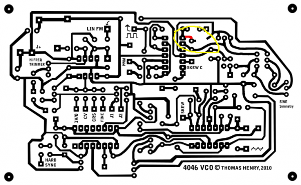
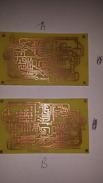
Sorry to necro post but I see a problem on the PCB you etched,I know because I just made the same mistake. I think I should of flipped or reversed the artwork for this board,before I made it with Press N Peel.As it is now & just like your board pics I think the Chips are backwards & upside down; meaning you would have to intstall your chip sockets on the copper side of the PCB in order for the pinouts to work.Keep in mind that the square pad is pin one on the IC . Anyone else care to comment.
| spitfire wrote: | Guys, I'm confused. I made PCB by myself, panel, everything as always. But I'm stuck on wiring. I see two J1, two J2, in schematic is writen to connect volt/octave to J1, but there's two of them on PCB, and also 1v/octave is writen there... I'm posting some pictures how my works look like. I hope you will help me. I don't want burn everything after such a nice working.


 |
|
|
|
Back to top
|
|
|
AlasdairMoons

Joined: Dec 03, 2011
Posts: 105
Location: East-Belgium
|
|
|
Back to top
|
|
|
AlasdairMoons
Joined: Dec 03, 2011
Posts: 105
Location: East-Belgium
|
|
|
Back to top
|
|
|
slacker
Joined: Nov 18, 2007
Posts: 301
Location: England
Audio files: 11
G2 patch files: 1
|
| Posted: Thu Jan 12, 2012 11:33 am Post subject:
|
|
|
| Yes, the XOR gate is part of the CD4046. Pins 14 and 3 are the inputs and 2 is the output. |
|
|
Back to top
|
|
|
01012k7
Joined: Aug 31, 2013
Posts: 25
Location: England
|
Posted: Sun Sep 22, 2013 6:58 am Post subject:
Re: X-4046 confusion
Subject description: Anyone else notice this? |
|
|
| Wobuse wrote: | Hey Spitfire...
Sorry to necro post but I see a problem on the PCB you etched,I know because I just made the same mistake. I think I should of flipped or reversed the artwork for this board,before I made it with Press N Peel.As it is now & just like your board pics I think the Chips are backwards & upside down; meaning you would have to intstall your chip sockets on the copper side of the PCB in order for the pinouts to work.Keep in mind that the square pad is pin one on the IC . Anyone else care to comment.
| spitfire wrote: | Guys, I'm confused. I made PCB by myself, panel, everything as always. But I'm stuck on wiring. I see two J1, two J2, in schematic is writen to connect volt/octave to J1, but there's two of them on PCB, and also 1v/octave is writen there... I'm posting some pictures how my works look like. I hope you will help me. I don't want burn everything after such a nice working.
|
|
so is the board the right way on this picture ???? |
|
|
Back to top
|
|
|
Antichambre

Joined: Oct 14, 2013
Posts: 2
Location: France
|
| Posted: Mon Oct 14, 2013 7:27 am Post subject:
x-4046 |
|
|
Hi everyone,
My x-4046 is built and works perfectly.
I drive it in pitch with a 12bit DAC, no problem for this part, now i need to digitally control the rampoid skew, i can't use a DCP for that, cause this last accepts only positive signal less than 5v.
Who can help me?
TIA... |
|
|
Back to top
|
|
|
elmegil

Joined: Mar 20, 2012
Posts: 2179
Location: Chicago
Audio files: 16
|
| Posted: Mon Oct 14, 2013 7:42 pm Post subject:
|
|
|
Crazy idea, probably too expensive, but I think it could work with the right parts.
Back to back vactrols. Have a DAC driving the first, and that same voltage going through an inverter to the second, so when one is bright the other is dark and vice versa.
Issues that need to be checked out: appropriate resistance values (500k sum?), trimming so that they are roughly equal, response curve of the vactrols (roughly linear? is non-linear a problem?), does the light memory/slow response of the vactrols cause you any concerns? |
|
|
Back to top
|
|
|
01012k7
Joined: Aug 31, 2013
Posts: 25
Location: England
|
|
|
Back to top
|
|
|
airfrankenstein
Joined: Jan 10, 2010
Posts: 62
Location: france
|
| Posted: Sat Feb 08, 2014 4:02 pm Post subject:
|
|
|
Hi,
Can someone verify my edit of the layout to see if it is correct?
I tried to take into account various revisions pointed out in the thread.
| Description: |
|

Download (listen) |
| Filename: |
thomas_henry_4046_vco_122_pnp_114.pdf |
| Filesize: |
1.99 MB |
| Downloaded: |
1991 Time(s) |
| Description: |
|
Download (listen) |
| Filename: |
thomas_henry_4046_vco_122_pnp_114.pdf |
| Filesize: |
1.99 MB |
| Downloaded: |
1953 Time(s) |
|
|
|
Back to top
|
|
|
mrmrshoes
Joined: Feb 19, 2011
Posts: 73
Location: Newcastle Upon Tyne
Audio files: 4
|
|
|
Back to top
|
|
|
airfrankenstein
Joined: Jan 10, 2010
Posts: 62
Location: france
|
| Posted: Tue Feb 11, 2014 4:34 am Post subject:
|
|
|
great, looks nice!
Can you pm me the eagle files then?
no problem bout the jumpers.
btw any thought s about this one in relation to the 555 vcl by TH?
Hard to find opinions. |
|
|
Back to top
|
|
|
mrmrshoes
Joined: Feb 19, 2011
Posts: 73
Location: Newcastle Upon Tyne
Audio files: 4
|
| Posted: Tue Feb 11, 2014 6:43 am Post subject:
|
|
|
No probs like
I've sent you a pm |
|
|
Back to top
|
|
|
airfrankenstein
Joined: Jan 10, 2010
Posts: 62
Location: france
|
| Posted: Wed Feb 12, 2014 10:40 am Post subject:
|
|
|
| thanks! |
|
|
Back to top
|
|
|
01012k7
Joined: Aug 31, 2013
Posts: 25
Location: England
|
| Posted: Wed Feb 12, 2014 3:57 pm Post subject:
|
|
|
| mrmrshoes wrote: | I've just built and tested my own pcb layout of this circuit and it works fine. I can give you the eagle files if you like.
They are a fair few jumpers, but that don't bother me like  |
would it be possible to send me the eagle files too  |
|
|
Back to top
|
|
|
airfrankenstein
Joined: Jan 10, 2010
Posts: 62
Location: france
|
| Posted: Wed Feb 12, 2014 4:02 pm Post subject:
|
|
|
| I'm having a hard time finding demo clips of the 4046. Fonik has one or two and that's about it. What existing vco would it be comparable to? |
|
|
Back to top
|
|
|
mrmrshoes
Joined: Feb 19, 2011
Posts: 73
Location: Newcastle Upon Tyne
Audio files: 4
|
| Posted: Fri Feb 14, 2014 6:47 pm Post subject:
|
|
|
| 01012k7 - check you pm like. |
|
|
Back to top
|
|
|
Designator
Joined: Jul 18, 2012
Posts: 9
Location: Northern Hemisphere
|
| Posted: Tue Mar 04, 2014 1:14 am Post subject:
|
|
|
| I'm interested in the Eagle files, too... |
|
|
Back to top
|
|
|
inlifeindeath

Joined: Apr 02, 2010
Posts: 316
Location: Albuquerque, NM
|
| Posted: Wed Mar 05, 2014 11:48 pm Post subject:
|
|
|
| airfrankenstein wrote: | | I'm having a hard time finding demo clips of the 4046. Fonik has one or two and that's about it. What existing vco would it be comparable to? |
ive built 3 X-4046 VCOs and they're fantastic. Fonik offers great PCBs.
it has all the classic necessities of a VCO, but the added feature I love and end up using the most is the 'Skew' pot. It allows you to morph a Sawtooth wave into a Triangle and everything in between, with a single pot. Want to make this voltage controlled at some point.
in summary, BUILD IT!
http://youtu.be/qwR22vLTc_8
_________________
http://www.youtube.com/user/borisandfef |
|
|
Back to top
|
|
|
fonik
Joined: Jun 07, 2006
Posts: 3950
Location: Germany
Audio files: 23
|
| Posted: Thu Mar 06, 2014 1:00 am Post subject:
|
|
|
| inlifeindeath wrote: | | ...but the added feature I love and end up using the most is the 'Skew' pot. It allows you to morph a Sawtooth wave into a Triangle and everything in between, with a single pot. Want to make this voltage controlled at some point. |
i put a x-pan/fader side by side with my x-4046 VCOs 
_________________
cheers,
matthias
____________
Big Boss at fonitronik
Tech Buddy at Random*Source |
|
|
Back to top
|
|
|
mrmrshoes
Joined: Feb 19, 2011
Posts: 73
Location: Newcastle Upon Tyne
Audio files: 4
|
| Posted: Thu Mar 06, 2014 10:41 am Post subject:
|
|
|
I'll post the eagle files later on the night when i get home, so if anyone else is interested they can just jump in.
If any one has a problem with me uploading these files please just let me know and i'll take them down.
i've got an 555 VCO layout thats tried and tested by a fair few people. I'll post this in its own thread if they's any takers? |
|
|
Back to top
|
|
|
mrmrshoes
Joined: Feb 19, 2011
Posts: 73
Location: Newcastle Upon Tyne
Audio files: 4
|
| Posted: Thu Mar 06, 2014 7:37 pm Post subject:
|
|
|
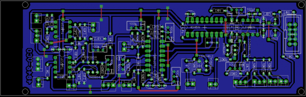
You'll need to compare TH schematics to mine for pot names, values, the odd jumper and a wee bit of off board wiring. Should be pretty easy to figure out.
A quick overview
All red traces on the board are jumper wires.
The one air wire from the expo transistors to the LF442 is also a jumper wire. (solder pads have been provided)
All off board wiring use 2 or 3 pin 0.1 header connectors (I really recommend these)
http://www.esr.co.uk/electronics/products/frame_connectors_pcb.htm
I would use eagle when building. you can highlight a part/trace in the schematic editor (show object button) and it will show up in the board editor. (really useful, i use it all the time)
two VCO's can be transferred onto on 160mm x 100m copper clad board
the freeware version of eagle allows you to export images from these files. The board dimensions are bigger than the the freeware limitations so you won't be able to edit without the full version.
This is how you prepare the artwork for Press n Peel
http://gaussmarkov.net/wordpress/tools/software/eagle/creating-a-pcb-image-using-export/
http://www.cnczone.com/forums/general_electronics_discussion/33374-eagle_pcb_image_toner_transfer_lil_tutorial.html
These file are for personal use only.
feel free to tweek and mod, if you make them better please post them here.
anyway have fun and happy building.
Also if anyone has a problem with me posting these files please just let me know. |
|
|
Back to top
|
|
|
|

 Forum index » DIY Hardware and Software » Thomas Henry designs