| Author |
Message |
9 volts
Joined: Jul 15, 2012
Posts: 28
Location: Au
|
 Posted: Sun Jul 15, 2012 6:29 am Post subject:
Sh5 Roland Posted: Sun Jul 15, 2012 6:29 am Post subject:
Sh5 Roland
Subject description: Drift |
  |
|
| Hello, my roland sh5 seems to drift (frequency),when I use the hold or sustain function. If I keep a keyboard note held down, drift does not occur. I have looked at schem, but a little confused as the hold and sustain/decay knobs are on different pcbs. I know first off to check voltages from the power pcb. But can't get my head around where to check voltage for the after key hold hold function. Any help appreciated. Thanks |
|
|
Back to top
|
|
 |
JingleJoe

Joined: Nov 10, 2011
Posts: 878
Location: Lancashire, England
Audio files: 14
|
| Posted: Sun Jul 15, 2012 9:17 am Post subject:
|
|
|
I asume the sustain and decay are the envelope controls? They will not affect the pitch of the oscillator, I'm going to propose that you have a bad capacitor or some bit of circuitry is drawing too much current from the hold capacitor. Assuming it uses the standard sample and hold arrangement.
_________________
As a mad scientist I am ruled by the dictum of science: "I could be wrong about this but lets find out"
Green Dungeon Alchemist Laboratories |
|
|
Back to top
|
|
|
9 volts
Joined: Jul 15, 2012
Posts: 28
Location: Au
|
| Posted: Sun Jul 15, 2012 4:36 pm Post subject:
|
|
|
| Thanks, it's not the sample hold function, it's the hold function that keeps the note playing when you take your fingers off the keyboard. So I suppose it's may be the voltage to oscillators when the keyboard voltage is not being used. |
|
|
Back to top
|
|
|
Peake

Joined: Jun 29, 2007
Posts: 1113
Location: Loss Angeles
Audio files: 3
|
| Posted: Sun Jul 15, 2012 10:34 pm Post subject:
|
|
|
Most keyboards use a sample-and-hold to maintain keyboard pitch once a key has been released. Check the schemos for main capacitor involved in this, maybe an FET. The portamento circuit as well.
_________________
We are selling emotions, there are no emotions in a grid. -mwagener
"IC 741. Sometimes you don't want fidelity." -Small Bear Electronics Catalog |
|
|
Back to top
|
|
|
stewpye
Joined: Apr 30, 2009
Posts: 49
Location: Brisbane, Australia
|
| Posted: Mon Jul 16, 2012 3:23 am Post subject:
|
|
|
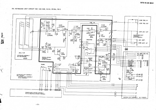
I'd try replacing C103 in the keyboard circuit unit. (page 13 of the service manual).
If this doesn't fix it check pin 1 of IC102 on the same board. If the voltage is drooping there I'd replace the FET pair and op amp with a low bias input FET op amp. |
|
|
Back to top
|
|
|
9 volts
Joined: Jul 15, 2012
Posts: 28
Location: Au
|
| Posted: Mon Jul 16, 2012 5:20 am Post subject:
|
|
|
| Thanks a lot. Given my some direction, and a place to start. I'll study these two areas of the service manual a little more and clear a space to pull the synth apart in the next week. You guys are great, thanks again. |
|
|
Back to top
|
|
|
radek tymecki
Joined: Mar 22, 2009
Posts: 85
Location: PL
|
| Posted: Mon Jul 16, 2012 6:40 am Post subject:
|
|
|
try to calibrate synth first 
Last edited by radek tymecki on Tue Jul 17, 2012 6:24 am; edited 1 time in total |
|
|
Back to top
|
|
|
stewpye
Joined: Apr 30, 2009
Posts: 49
Location: Brisbane, Australia
|
| Posted: Mon Jul 16, 2012 1:15 pm Post subject:
|
|
|
| radek tymecki wrote: | | try to calibrate synth first |
Not a bad idea, but the symptom he described points to S&H circuit which doesn't require calibration, and if he's not familiar with calibration he could make things worse (temporarily).
It would be worth at least checking the power supply voltages, and the +10V and -10V.
Regards,
Stewart. |
|
|
Back to top
|
|
|
9 volts
Joined: Jul 15, 2012
Posts: 28
Location: Au
|
| Posted: Sun Aug 26, 2012 1:56 am Post subject:
|
|
|
| I finally got some time to dismantle the sh5 today. The c103 appears to be ok- keyboard circuit as mentioned above(tested). So now I am looking at the sample hold circuit and 10v circuit. Thank again for the advice |
|
|
Back to top
|
|
|
9 volts
Joined: Jul 15, 2012
Posts: 28
Location: Au
|
| Posted: Sun Aug 26, 2012 3:23 am Post subject:
|
|
|
Checked the 10- and 10+ voltage which were ok.
Last edited by 9 volts on Mon Aug 27, 2012 7:02 pm; edited 1 time in total |
|
|
Back to top
|
|
|
9 volts
Joined: Jul 15, 2012
Posts: 28
Location: Au
|
| Posted: Sun Aug 26, 2012 4:41 am Post subject:
|
|
|
| I have just tested the sample and voltage voltage adjustment (pg 35) and the output voltage definitely gradually drifts upwards. So I suppose now I test all the the capacitors in this area......I'm getting a little out of my depth so if anyone has any advice greatly appreciate it. Thanks |
|
|
Back to top
|
|
|
ian-s

Joined: Apr 01, 2004
Posts: 2672
Location: Auckland, New Zealand
Audio files: 42
G2 patch files: 626
|
| Posted: Sun Aug 26, 2012 1:00 pm Post subject:
|
|
|
| A little drift is normal. It is supposed to just hold the pitch while the release times out. The minimoog drifted a lot but it was only a problem when external triggering was used. I used to wedge a key down with a patch cord to fix that problem. |
|
|
Back to top
|
|
|
9 volts
Joined: Jul 15, 2012
Posts: 28
Location: Au
|
| Posted: Sun Aug 26, 2012 6:08 pm Post subject:
|
|
|
I replaced a faulty diode in the sample hold section(covered in glue). This got the samplehold adjustment voltage stable, however didn't alter the drift problem.
But I am going to recheck the portamento section again as rereading the manual I realize there is also a hold function around there also......so will recheck voltages around there tonight. (my misunderstanding)
Thanks for the comment. I have used a basic sh1000 which hardly drifted- the sh5 is rising a little faster than I would expect. |
|
|
Back to top
|
|
|
9 volts
Joined: Jul 15, 2012
Posts: 28
Location: Au
|
| Posted: Mon Aug 27, 2012 3:52 am Post subject:
|
|
|
| Tonight I tested c103 (capacitor mentioned above) again. It tests ok with capacitance tester (dm meter). I tried to do a voltage test across it but the meter influenced the voltage- when meter was connected the voltage kept dropping-opposite of what normally happens- frequency lowered. I then tested pin 1 of ic102 as mentioned above- the voltage continues to rise after a key is pushed at about .01 volt per second. (causing the frequency to rise). I will buy a .33mf capacitor to try (c103) and maybe c104 also? (10uf). Definitely seems like the problem area. |
|
|
Back to top
|
|
|
9 volts
Joined: Jul 15, 2012
Posts: 28
Location: Au
|
| Posted: Tue Aug 28, 2012 3:58 am Post subject:
|
|
|
| Well, tonight I tried a new c103 (hold capacitor) which didn't any difference. So I suppose I will have to look at it in a little more depth (learning curve) |
|
|
Back to top
|
|
|
JingleJoe
Joined: Nov 10, 2011
Posts: 878
Location: Lancashire, England
Audio files: 14
|
| Posted: Tue Aug 28, 2012 5:05 am Post subject:
|
|
|
I've been followng this thread to see what you come up with but I feel I should pipe up now, if the voltage is increasing then the hold cap is getting voltage from somewhere. What op amp is it connected to? I assume it is connected to an op amp wired up as a voltage follower, or perhapsc some sort of dedicated analogue buffer?
_________________
As a mad scientist I am ruled by the dictum of science: "I could be wrong about this but lets find out"
Green Dungeon Alchemist Laboratories |
|
|
Back to top
|
|
|
9 volts
Joined: Jul 15, 2012
Posts: 28
Location: Au
|
| Posted: Tue Aug 28, 2012 5:24 am Post subject:
|
|
|
A ca1458 (1c101B) then a 2sk30a (tr101) then the hold capacitor. I have just done a few more tests. The voltage coming out of the ca1458/into the 2sk30a is constant, the voltage leaving the 2sk30a is not (everything beyond this point rises etc). I'm thinking it's probably worth trying a 2sk30a replacement.
(B+ and- and 10- and+ at the entry point on this board have been tested and are ok).
Thanks for getting back to me.
My basic understanding is that the 2sk30a should lock the voltage? |
|
|
Back to top
|
|
|
JingleJoe
Joined: Nov 10, 2011
Posts: 878
Location: Lancashire, England
Audio files: 14
|
| Posted: Tue Aug 28, 2012 11:08 am Post subject:
|
|
|
The transistor in question (or perhaps FET) charges or discharges the capacitor to the voltage coming from the keyboard. However your layout description makes mea little dubious.
The op amp, which I suspected might be a CA series op amp, is a probably high impedance buffer AKA voltage follower which can output the same voltage as the capacitor, without discharging it. However from the datasheet it looks like the input impedance is a bit low for that sort of application. The CA3140 is a good high impedance input op amp.
I should have asked right away, but do you have a circuit diagram to refer to? It would clarify a lot.
_________________
As a mad scientist I am ruled by the dictum of science: "I could be wrong about this but lets find out"
Green Dungeon Alchemist Laboratories |
|
|
Back to top
|
|
|
9 volts
Joined: Jul 15, 2012
Posts: 28
Location: Au
|
|
|
Back to top
|
|
|
9 volts
Joined: Jul 15, 2012
Posts: 28
Location: Au
|
| Posted: Wed Aug 29, 2012 3:16 am Post subject:
|
|
|
| I've got a few tl072 ics here, would it be worth trying one? I figure at least to see if it changes the synths behaviour. Thanks for the description, I understand now that if the k30a transistor was faulty probably more issues would arise than what I have. Thanks again |
|
|
Back to top
|
|
|
stewpye
Joined: Apr 30, 2009
Posts: 49
Location: Brisbane, Australia
|
| Posted: Wed Aug 29, 2012 1:13 pm Post subject:
|
|
|
There's a good chance the problem could be the buffer consisting of TR102 and IC102A. Since you probably can't a replacement for TR102 easily I'd suggest carefully removing it and IC102 and replacing IC102 with a low bias input, low offset FET dual op amp.
Remove R106 and R107.
Leave out TR102.
Join gate-source pads of both FET's. (ie:C103 will go to pin 3 of the op amp, join pin 1 and 2 of the op amp).
If you put a socket in for the op amp you could try the TL072. The TL072BC actually has better offset voltage specs than the CA1458. The OPA2134 would be better, and there would be even better choices than that. You want the lowest input bias possible so as not to drag down the S&H cap voltage. This was the reason for having the dual FET there.
Regards,
Stewart. |
|
|
Back to top
|
|
|
JingleJoe
Joined: Nov 10, 2011
Posts: 878
Location: Lancashire, England
Audio files: 14
|
| Posted: Wed Aug 29, 2012 1:51 pm Post subject:
|
|
|
| stewpye wrote: | | There's a good chance the problem could be the buffer consisting of TR102 and IC102A. |
That's what I was thinking, good suggestions too.
I reckon voltage may be leaking in from that FET pair (TR102) However I am also wondering what the voltage is like on the gate of TR101, Personally I'd like to probe that. D101 will keep it low or negative but if that diode is faulty it could be turning on TR101 when it shouldn't and allowing in some stray voltages, so I'd also like to probe the output of IC101B and see what's happening there. I know you mentioned it's output voltage is constant but what is it constantly? positive? negative? 5 volts? 0.5 volts?
_________________
As a mad scientist I am ruled by the dictum of science: "I could be wrong about this but lets find out"
Green Dungeon Alchemist Laboratories |
|
|
Back to top
|
|
|
9 volts
Joined: Jul 15, 2012
Posts: 28
Location: Au
|
| Posted: Thu Aug 30, 2012 2:41 am Post subject:
|
|
|
Thanks for the advice. I will try it out next weekend (buy an ic socket and also a burr brown).
I've just done a few more voltage tests. By constant voltage I meant stable (does not drift).
ic101
pin1 = 3.66
pin2 = 0
pin3 = 0
pin 5 = 1.29
pin6&7 = 2.65
fet (tr101)
gate (from diode 101) = -13.57
source (from ic 101 pin7) 2.65 (influenced by note on then returns to 2.65 after note released)
diode 101
-13.94 (when note is pushed becomes 13.94)
-13.57 (to gate)
Thanks again |
|
|
Back to top
|
|
|
9 volts
Joined: Jul 15, 2012
Posts: 28
Location: Au
|
| Posted: Fri Aug 31, 2012 5:41 am Post subject:
|
|
|
| Just a quick note to say I tried the mentioned rewiring tonight (got rid of tr102 etc) and it has fixed the problem! Thanks to everyone for your advice! It now losses about .01v per 1.30 mins which seems alot more like the kind of behaviour i would expect (slow droop). I may experiment with cap size while I have the synth pulled apart. Thanks again there is no way I could have done this without your help! |
|
|
Back to top
|
|
|
stewpye
Joined: Apr 30, 2009
Posts: 49
Location: Brisbane, Australia
|
| Posted: Fri Aug 31, 2012 1:18 pm Post subject:
|
|
|
Good to hear. I'll remember that in case I ever have the same problem with my SH5.
Regards,
Stew. |
|
|
Back to top
|
|
|
|

 Forum index » DIY Hardware and Software