| Author |
Message |
Inventor
Stream Operator

Joined: Oct 13, 2007
Posts: 6221
Location: near Austin, Tx, USA
Audio files: 267
|
|
|
Back to top
|
|
 |
Inventor
Stream Operator

Joined: Oct 13, 2007
Posts: 6221
Location: near Austin, Tx, USA
Audio files: 267
|
|
|
Back to top
|
|
 |
Inventor
Stream Operator

Joined: Oct 13, 2007
Posts: 6221
Location: near Austin, Tx, USA
Audio files: 267
|
 Posted: Fri Oct 04, 2019 10:17 am Post subject: Posted: Fri Oct 04, 2019 10:17 am Post subject:
|
  |
|
Addendum: please be aware that I've gotten into some quandries running amok regarding making time to take the next step, so it will be a short while before I can post a progress update.
Yours truly,
Les
_________________
"Let's make noise for peace." - Kijjaz |
|
|
Back to top
|
|
 |
Inventor
Stream Operator

Joined: Oct 13, 2007
Posts: 6221
Location: near Austin, Tx, USA
Audio files: 267
|
 Posted: Thu Oct 10, 2019 3:14 pm Post subject: Posted: Thu Oct 10, 2019 3:14 pm Post subject:
|
  |
|
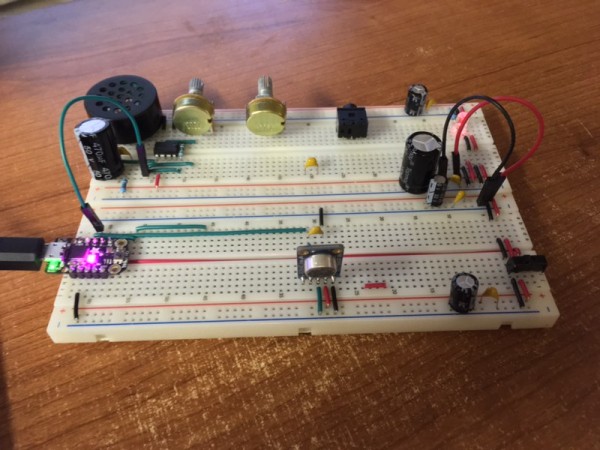
Success! Why such excitement? Read on... The short story is that the circuit has the behavior of a self-limited feedback squeal with more than a few applications.
Running on USB instead of other power sources makes this design easy to operate by computer, powered hub, or wall socket power source. This +5V connection is routed from the M0 Trinket PCB to all the other sub circuits. The feedback loop consists of a microphone, the microcontroller,and an LM386 speaker driver.
Around and around goes the signal; mic to Trinket to speaker and back to the mic, etc. Lather, rinse, repeat as they say. In the feedback path we have delay in the Trinket that sets the electronic frequency and another source of frequency regulaton. These work together to cause some fun interactions like speaking into the mic and having the voice all morphed and mixed with the feedback; holding hands in proximity to the mic and speaker for a Thevenin-like behavior, and other fun tricks.
Have a look at the two photos below showing the final circuit. Note that some of the parts near the center are unused as they are spares or planned for future involvement. The connected photo shows how the circuit was originally created, and the separated photo shows a fortunate happenstance in which the speaker and mic can be placed apart for different (and measurably consistent) behavior.
On the upper left we have our LM386 speaker driver with gain pot for trimming behavior of the loop. Well, there are lots of other details to discuss, too many for one post so I'll be back soon with more observations and descriptions. Until then, farewell and happy breadboarding!
Yours truly,
Les
| Description: |
| Breadboards fully separated |
|
| Filesize: |
105.77 KB |
| Viewed: |
409 Time(s) |
| This image has been reduced to fit the page. Click on it to enlarge. |

|
| Description: |
| Breadboards connected together |
|
| Filesize: |
113.78 KB |
| Viewed: |
404 Time(s) |
| This image has been reduced to fit the page. Click on it to enlarge. |

|
_________________
"Let's make noise for peace." - Kijjaz |
|
|
Back to top
|
|
 |
|

