| Author |
Message |
floating-water
Joined: Oct 06, 2020
Posts: 62
Location: UK
|
 Posted: Fri Nov 13, 2020 7:29 pm Post subject:
turning old piano into midi keyboard (keyboard matrix) Posted: Fri Nov 13, 2020 7:29 pm Post subject:
turning old piano into midi keyboard (keyboard matrix) |
  |
|
I've come across articles on this and I've tried to understand it but I'm struggling to understand how to implement it with the gear I have. I'm looking to use these keys with a synth i'm building through midi to cv I guess.
I understand I need a multiplexer and an arduino or microcontroller and that the keys are usually organised in columns and rows. The pics are the keyboard im working with, its 61 keys and seems to have two ribbon connections coming off it, both with 8 output pins coming off of them which seems easy enough? I wrote out a table in a way I think I understand it but how on earth do I go about implementing this?


Is there a Vcc and ground coming out of the ribbon cables? If so that changes the number of outputs? How do I know which is columns and rows?
Appreciate any help
Thx
 |
|
|
Back to top
|
|
 |
PHOBoS
Joined: Jan 14, 2010
Posts: 5898
Location: Moon Base
Audio files: 709
|
| Posted: Sat Nov 14, 2020 6:26 am Post subject:
|
|
|
For a keyboard matrix you will have to send a voltage in sequence to the rows and for every row scan all the columns.
send a voltage to row 1, read the voltages from column 1 to 8
send a voltage to row 2, read the voltages from column 1 to 8
send a voltage to row 3, read the voltages from column 1 to 8
etc,..
note that unless the keyboard itself already has diodes or other components you can swap rows/columns. So you could also
send a voltage to the columns and read the rows.
what you need to watch out for is that if you don't send a voltage to a row it has to be unconnected or high impedance.
So don't just send high an low signals as this can lead to shorts. A mux would be an easy way to do this though you could
also use transistors or even diodes. There is also things like ghosting and blocking that you have to keep in mind but you
should find that out along the way. Here's something to start with https://deskthority.net/wiki/Rollover,_blocking_and_ghosting
_________________
"My perf, it's full of holes!"
http://phobos.000space.com/
SoundCloud BandCamp MixCloud Stickney Synthyards Captain Collider Twitch YouTube |
|
|
Back to top
|
|
|
floating-water
Joined: Oct 06, 2020
Posts: 62
Location: UK
|
| Posted: Sat Nov 14, 2020 7:06 am Post subject:
|
|
|
| Yes my guy Phobos. Is there importance in the actual voltage reading? I don't even own a multi-meter yet, in theory could I attach each pin to breadboard for row, for column and say use an led to get a response off the columns? |
|
|
Back to top
|
|
|
PHOBoS
Joined: Jan 14, 2010
Posts: 5898
Location: Moon Base
Audio files: 709
|
| Posted: Sat Nov 14, 2020 8:42 am Post subject:
|
|
|
well if you use a microcontroller then the voltage needs to be compatable for that which is usually 5V for an Arduino.
I did notice some diodes on the PCB so you will have to check how those are connected determine what to use as rows/columns.
Not sure what you want to do with LEDs. I guess you could test turning them on with keys but you have to keep the current low
with those membrane switches so I would recommend to use transistors or other buffers to drive the LEDs.
_________________
"My perf, it's full of holes!"
http://phobos.000space.com/
SoundCloud BandCamp MixCloud Stickney Synthyards Captain Collider Twitch YouTube |
|
|
Back to top
|
|
|
Grumble
Joined: Nov 23, 2015
Posts: 1320
Location: Netherlands
Audio files: 30
|
| Posted: Sat Nov 14, 2020 4:16 pm Post subject:
|
|
|

To clarify what Phobos wrote.
_________________
my synth |
|
|
Back to top
|
|
|
floating-water
Joined: Oct 06, 2020
Posts: 62
Location: UK
|
| Posted: Sun Nov 15, 2020 2:00 am Post subject:
|
|
|
ok i broke my eyes and followed the traces on the board:
found 7 groups of 8 keys and 1 group of 5 -> connected to the bottom ribbon cable and to the keys
and 5 groups of 8 and 3 groups of 7 -> connected to the top ribbon cable and to the diodes
so judging by the numbers the table i wrote must be correct?
in that diagram above, the diodes face the rows and in this keyboard, the diodes face the top ribbon cable so the top is the rows? does that mean they are pull up?
and what would be an implementation you would recommend, shift register? |
|
|
Back to top
|
|
|
floating-water
Joined: Oct 06, 2020
Posts: 62
Location: UK
|
| Posted: Sun Nov 15, 2020 3:27 am Post subject:
|
|
|
so id put the 8 rows into digital pins on atmega(arduino), the 8 columns go into shift register inputs
the clock, latch and data from the register goes into the arduino digi pins
besides modifying the amount of rows/columns in this code is there anything else I need modify?
| Code: | #define NUM_ROWS 8
#define NUM_COLS 8
#define NOTE_ON_CMD 0x90
#define NOTE_OFF_CMD 0x80
#define NOTE_VELOCITY 127
//MIDI baud rate
#define SERIAL_RATE 31250
// Pin Definitions
// Row input pins
const int row1Pin = 2;
const int row2Pin = 3;
const int row3Pin = 4;
const int row4Pin = 5;
const int row5Pin = 6;
const int row6Pin = 7;
const int row7Pin = 8;
const int row8Pin = 9;
// 74HC595 pins
const int dataPin = 8;
const int latchPin = 9;
const int clockPin = 10;
boolean keyPressed[NUM_ROWS][NUM_COLS];
uint8_t keyToMidiMap[NUM_ROWS][NUM_COLS];
// bitmasks for scanning columns
int bits[] =
{
B11111110,
B11111101,
B11111011,
B11110111,
B11101111,
B11011111,
B10111111,
B01111111
};
void setup()
{
int note = 31;
for(int colCtr = 0; colCtr < NUM_COLS; ++colCtr)
{
for(int rowCtr = 0; rowCtr < NUM_ROWS; ++rowCtr)
{
keyPressed[rowCtr][colCtr] = false;
keyToMidiMap[rowCtr][colCtr] = note;
note++;
}
}
// setup pins output/input mode
pinMode(dataPin, OUTPUT);
pinMode(clockPin, OUTPUT);
pinMode(latchPin, OUTPUT);
pinMode(row1Pin, INPUT);
pinMode(row2Pin, INPUT);
pinMode(row3Pin, INPUT);
pinMode(row4Pin, INPUT);
pinMode(row5Pin, INPUT);
pinMode(row6Pin, INPUT);
pinMode(row7Pin, INPUT);
pinMode(row8Pin, INPUT);
Serial.begin(SERIAL_RATE);
}
void loop()
{
for (int colCtr = 0; colCtr < NUM_COLS; ++colCtr)
{
//scan next column
scanColumn(colCtr);
//get row values at this column
int rowValue[NUM_ROWS];
rowValue[0] = !digitalRead(row1Pin);
rowValue[1] = !digitalRead(row2Pin);
rowValue[2] = !digitalRead(row3Pin);
rowValue[3] = !digitalRead(row4Pin);
rowValue[4] = !digitalRead(row5Pin);
rowValue[5] = !digitalRead(row6Pin);
// process keys pressed
for(int rowCtr=0; rowCtr<NUM_ROWS; ++rowCtr)
{
if(rowValue[rowCtr] != 0 && !keyPressed[rowCtr][colCtr])
{
keyPressed[rowCtr][colCtr] = true;
noteOn(rowCtr,colCtr);
}
}
// process keys released
for(int rowCtr=0; rowCtr<NUM_ROWS; ++rowCtr)
{
if(rowValue[rowCtr] == 0 && keyPressed[rowCtr][colCtr])
{
keyPressed[rowCtr][colCtr] = false;
noteOff(rowCtr,colCtr);
}
}
}
}
void scanColumn(int colNum)
{
digitalWrite(latchPin, LOW);
if(0 <= colNum && colNum <= 7)
{
shiftOut(dataPin, clockPin, MSBFIRST, B11111111); //right sr
shiftOut(dataPin, clockPin, MSBFIRST, bits[colNum]); //left sr
}
else
{
shiftOut(dataPin, clockPin, MSBFIRST, bits[colNum-8]); //right sr
shiftOut(dataPin, clockPin, MSBFIRST, B11111111); //left sr
}
digitalWrite(latchPin, HIGH);
}
void noteOn(int row, int col)
{
Serial.write(NOTE_ON_CMD);
Serial.write(keyToMidiMap[row][col]);
Serial.write(NOTE_VELOCITY);
}
void noteOff(int row, int col)
{
Serial.write(NOTE_OFF_CMD);
Serial.write(keyToMidiMap[row][col]);
Serial.write(NOTE_VELOCITY);
} |
|
|
|
Back to top
|
|
|
PHOBoS
Joined: Jan 14, 2010
Posts: 5898
Location: Moon Base
Audio files: 709
|
|
|
Back to top
|
|
|
floating-water
Joined: Oct 06, 2020
Posts: 62
Location: UK
|
| Posted: Sun Nov 15, 2020 10:11 am Post subject:
|
|
|
ah ye that will be me bein a dumbass, i got the base code from an instructable and started making changes quickly so it be (?):
| Code: | #define NUM_ROWS 8
#define NUM_COLS 8
#define NOTE_ON_CMD 0x90
#define NOTE_OFF_CMD 0x80
#define NOTE_VELOCITY 127
//MIDI baud rate
#define SERIAL_RATE 31250
// Pin Definitions
// Row input pins
const int row1Pin = 2;
const int row2Pin = 3;
const int row3Pin = 4;
const int row4Pin = 5;
const int row5Pin = 6;
const int row6Pin = 7;
const int row7Pin = 8;
const int row8Pin = 9;
// 74HC595 pins
const int dataPin = 10;
const int latchPin = 11;
const int clockPin = 12;
boolean keyPressed[NUM_ROWS][NUM_COLS];
uint8_t keyToMidiMap[NUM_ROWS][NUM_COLS];
// bitmasks for scanning columns
int bits[] =
{
B11111110,
B11111101,
B11111011,
B11110111,
B11101111,
B11011111,
B10111111,
B01111111
};
void setup()
{
int note = 31;
for(int colCtr = 0; colCtr < NUM_COLS; ++colCtr)
{
for(int rowCtr = 0; rowCtr < NUM_ROWS; ++rowCtr)
{
keyPressed[rowCtr][colCtr] = false;
keyToMidiMap[rowCtr][colCtr] = note;
note++;
}
}
// setup pins output/input mode
pinMode(dataPin, OUTPUT);
pinMode(clockPin, OUTPUT);
pinMode(latchPin, OUTPUT);
pinMode(row1Pin, INPUT);
pinMode(row2Pin, INPUT);
pinMode(row3Pin, INPUT);
pinMode(row4Pin, INPUT);
pinMode(row5Pin, INPUT);
pinMode(row6Pin, INPUT);
pinMode(row7Pin, INPUT);
pinMode(row8Pin, INPUT);
Serial.begin(SERIAL_RATE);
}
void loop()
{
for (int colCtr = 0; colCtr < NUM_COLS; ++colCtr)
{
//scan next column
scanColumn(colCtr);
//get row values at this column
int rowValue[NUM_ROWS];
rowValue[0] = !digitalRead(row1Pin);
rowValue[1] = !digitalRead(row2Pin);
rowValue[2] = !digitalRead(row3Pin);
rowValue[3] = !digitalRead(row4Pin);
rowValue[4] = !digitalRead(row5Pin);
rowValue[5] = !digitalRead(row6Pin);
// process keys pressed
for(int rowCtr=0; rowCtr<NUM_ROWS; ++rowCtr)
{
if(rowValue[rowCtr] != 0 && !keyPressed[rowCtr][colCtr])
{
keyPressed[rowCtr][colCtr] = true;
noteOn(rowCtr,colCtr);
}
}
// process keys released
for(int rowCtr=0; rowCtr<NUM_ROWS; ++rowCtr)
{
if(rowValue[rowCtr] == 0 && keyPressed[rowCtr][colCtr])
{
keyPressed[rowCtr][colCtr] = false;
noteOff(rowCtr,colCtr);
}
}
}
}
void scanColumn(int colNum)
{
digitalWrite(latchPin, LOW);
if(0 <= colNum && colNum <= 7)
{
shiftOut(dataPin, clockPin, MSBFIRST, B11111111); //right sr
shiftOut(dataPin, clockPin, MSBFIRST, bits[colNum]); //left sr
}
else
{
shiftOut(dataPin, clockPin, MSBFIRST, bits[colNum-8]); //right sr
shiftOut(dataPin, clockPin, MSBFIRST, B11111111); //left sr
}
digitalWrite(latchPin, HIGH);
}
void noteOn(int row, int col)
{
Serial.write(NOTE_ON_CMD);
Serial.write(keyToMidiMap[row][col]);
Serial.write(NOTE_VELOCITY);
}
void noteOff(int row, int col)
{
Serial.write(NOTE_OFF_CMD);
Serial.write(keyToMidiMap[row][col]);
Serial.write(NOTE_VELOCITY);
} |
i've only changed the really obvious stuff at the top of the code, ive never done code before so ye if u have another look for me that be  . I can see where they probably should be changed but needs to be right obvs, thx for the draw up there btw . I can see where they probably should be changed but needs to be right obvs, thx for the draw up there btw |
|
|
Back to top
|
|
|
PHOBoS
Joined: Jan 14, 2010
Posts: 5898
Location: Moon Base
Audio files: 709
|
| Posted: Sun Nov 15, 2020 12:36 pm Post subject:
|
|
|
some things I've noticed sofar
- the number of columns and rows should probably be set to 7, not 8 as it starts from 0
- the initial note value is set to 31 which is a G (octave 0) so its value depends on the layout of the keyboard and
what you want the lowest octave to be. You could add switches or something else later to make this adjustable.
- the function 'scanColumn(int colNum)' can be simplified since you only have 8 columns.
- there is some inversion going on, not sure yet what's up with that. Do you have a link to the instructable ?
_________________
"My perf, it's full of holes!"
http://phobos.000space.com/
SoundCloud BandCamp MixCloud Stickney Synthyards Captain Collider Twitch YouTube |
|
|
Back to top
|
|
|
floating-water
Joined: Oct 06, 2020
Posts: 62
Location: UK
|
| Posted: Sun Nov 15, 2020 1:02 pm Post subject:
|
|
|
ah okok was curious how to set the first note. just gonna keep editing and pasting the code so i can keep track if ok
| Code: | #define NUM_ROWS 7
#define NUM_COLS 7
#define NOTE_ON_CMD 0x90
#define NOTE_OFF_CMD 0x80
#define NOTE_VELOCITY 127
//MIDI baud rate
#define SERIAL_RATE 31250
// Pin Definitions
// Row input pins
const int row1Pin = 2;
const int row2Pin = 3;
const int row3Pin = 4;
const int row4Pin = 5;
const int row5Pin = 6;
const int row6Pin = 7;
const int row7Pin = 8;
const int row8Pin = 9;
// 74HC595 pins
const int dataPin = 10;
const int latchPin = 11;
const int clockPin = 12;
boolean keyPressed[NUM_ROWS][NUM_COLS];
uint8_t keyToMidiMap[NUM_ROWS][NUM_COLS];
// bitmasks for scanning columns
int bits[] =
{
B11111110,
B11111101,
B11111011,
B11110111,
B11101111,
B11011111,
B10111111,
B01111111
};
void setup()
{
int note = 36;
for(int colCtr = 0; colCtr < NUM_COLS; ++colCtr)
{
for(int rowCtr = 0; rowCtr < NUM_ROWS; ++rowCtr)
{
keyPressed[rowCtr][colCtr] = false;
keyToMidiMap[rowCtr][colCtr] = note;
note++;
}
}
// setup pins output/input mode
pinMode(dataPin, OUTPUT);
pinMode(clockPin, OUTPUT);
pinMode(latchPin, OUTPUT);
pinMode(row1Pin, INPUT);
pinMode(row2Pin, INPUT);
pinMode(row3Pin, INPUT);
pinMode(row4Pin, INPUT);
pinMode(row5Pin, INPUT);
pinMode(row6Pin, INPUT);
pinMode(row7Pin, INPUT);
pinMode(row8Pin, INPUT);
Serial.begin(SERIAL_RATE);
}
void loop()
{
for (int colCtr = 0; colCtr < NUM_COLS; ++colCtr)
{
//scan next column
scanColumn(colCtr);
//get row values at this column
int rowValue[NUM_ROWS];
rowValue[0] = !digitalRead(row1Pin);
rowValue[1] = !digitalRead(row2Pin);
rowValue[2] = !digitalRead(row3Pin);
rowValue[3] = !digitalRead(row4Pin);
rowValue[4] = !digitalRead(row5Pin);
rowValue[5] = !digitalRead(row6Pin);
// process keys pressed
for(int rowCtr=0; rowCtr<NUM_ROWS; ++rowCtr)
{
if(rowValue[rowCtr] != 0 && !keyPressed[rowCtr][colCtr])
{
keyPressed[rowCtr][colCtr] = true;
noteOn(rowCtr,colCtr);
}
}
// process keys released
for(int rowCtr=0; rowCtr<NUM_ROWS; ++rowCtr)
{
if(rowValue[rowCtr] == 0 && keyPressed[rowCtr][colCtr])
{
keyPressed[rowCtr][colCtr] = false;
noteOff(rowCtr,colCtr);
}
}
}
}
void scanColumn(int colNum)
{
digitalWrite(latchPin, LOW);
if(0 <= colNum && colNum <= 7)
{
shiftOut(dataPin, clockPin, MSBFIRST, B11111111); //right sr
shiftOut(dataPin, clockPin, MSBFIRST, bits[colNum]); //left sr
}
else
{
shiftOut(dataPin, clockPin, MSBFIRST, bits[colNum-8]); //right sr
shiftOut(dataPin, clockPin, MSBFIRST, B11111111); //left sr
}
digitalWrite(latchPin, HIGH);
}
void noteOn(int row, int col)
{
Serial.write(NOTE_ON_CMD);
Serial.write(keyToMidiMap[row][col]);
Serial.write(NOTE_VELOCITY);
}
void noteOff(int row, int col)
{
Serial.write(NOTE_OFF_CMD);
Serial.write(keyToMidiMap[row][col]);
Serial.write(NOTE_VELOCITY);
} |
what about this bit:
| Code: | // setup pins output/input mode
pinMode(dataPin, OUTPUT);
pinMode(clockPin, OUTPUT);
pinMode(latchPin, OUTPUT);
pinMode(row1Pin, INPUT);
pinMode(row2Pin, INPUT);
pinMode(row3Pin, INPUT);
pinMode(row4Pin, INPUT);
pinMode(row5Pin, INPUT);
pinMode(row6Pin, INPUT);
pinMode(row7Pin, INPUT);
pinMode(row8Pin, INPUT);
Serial.begin(SERIAL_RATE);
}
void loop()
{
for (int colCtr = 0; colCtr < NUM_COLS; ++colCtr)
{
//scan next column
scanColumn(colCtr);
//get row values at this column
int rowValue[NUM_ROWS];
rowValue[0] = !digitalRead(row1Pin);
rowValue[1] = !digitalRead(row2Pin);
rowValue[2] = !digitalRead(row3Pin);
rowValue[3] = !digitalRead(row4Pin);
rowValue[4] = !digitalRead(row5Pin);
rowValue[5] = !digitalRead(row6Pin); |
https://www.instructables.com/Add-MIDI-port-to-Keyboard/
really good instructable, its still all new to me tho. theres a deleted video where he supposedly explained the areas o fthe code to adjust
is the scanColumn(int colNum) to do with daisy chaining the shift registers? |
|
|
Back to top
|
|
|
PHOBoS
Joined: Jan 14, 2010
Posts: 5898
Location: Moon Base
Audio files: 709
|
| Posted: Sun Nov 15, 2020 4:57 pm Post subject:
|
|
|
thanks for the link, I'll check the instructable.
| Quote: | | is the scanColumn(int colNum) to do with daisy chaining the shift registers? |
yes, if you look at this section:
| Code: | void scanColumn(int colNum)
{
digitalWrite(latchPin, LOW);
if(0 <= colNum && colNum <= 7)
{
shiftOut(dataPin, clockPin, MSBFIRST, B11111111); //right sr
shiftOut(dataPin, clockPin, MSBFIRST, bits[colNum]); //left sr
}
else
{
shiftOut(dataPin, clockPin, MSBFIRST, bits[colNum-8]); //right sr
shiftOut(dataPin, clockPin, MSBFIRST, B11111111); //left sr
}
digitalWrite(latchPin, HIGH);
} |
it checks if the column is between 0 and 7 in which case it uses the left shiftregister else it uses the right shift register.
But you only have 8 columns and 1 shiftregister so you only need:
| Code: | void scanColumn(int colNum)
{
digitalWrite(latchPin, LOW);
shiftOut(dataPin, clockPin, MSBFIRST, bits[colNum]); //left sr
digitalWrite(latchPin, HIGH);
} |
now here's where it's a bit strange as the bits[colNum] value sets all the outputs to 1 except the one it wants to read
and then it inverts the reading. I don't think that can work in your case because of the diodes.
oh and this section:
| Code: |
//get row values at this column
int rowValue[NUM_ROWS];
rowValue[0] = !digitalRead(row1Pin);
rowValue[1] = !digitalRead(row2Pin);
rowValue[2] = !digitalRead(row3Pin);
rowValue[3] = !digitalRead(row4Pin);
rowValue[4] = !digitalRead(row5Pin);
rowValue[5] = !digitalRead(row6Pin);
|
will have to be extended for 8 rows (note that the ! is responsable for inverting the readings)
_________________
"My perf, it's full of holes!"
http://phobos.000space.com/
SoundCloud BandCamp MixCloud Stickney Synthyards Captain Collider Twitch YouTube |
|
|
Back to top
|
|
|
floating-water
Joined: Oct 06, 2020
Posts: 62
Location: UK
|
| Posted: Sun Nov 15, 2020 7:29 pm Post subject:
|
|
|
right right ok fascinating. is it just the exclamations that initiate the inversion? so if a board didn't have diodes you could invert the readings through the code to prevent ghosting?
| Code: | #define NUM_ROWS 7
#define NUM_COLS 7
#define NOTE_ON_CMD 0x90
#define NOTE_OFF_CMD 0x80
#define NOTE_VELOCITY 127
//MIDI baud rate
#define SERIAL_RATE 31250
// Pin Definitions
// Row input pins
const int row1Pin = 2;
const int row2Pin = 3;
const int row3Pin = 4;
const int row4Pin = 5;
const int row5Pin = 6;
const int row6Pin = 7;
const int row7Pin = 8;
const int row8Pin = 9;
// 74HC595 pins
const int dataPin = 10;
const int latchPin = 11;
const int clockPin = 12;
boolean keyPressed[NUM_ROWS][NUM_COLS];
uint8_t keyToMidiMap[NUM_ROWS][NUM_COLS];
// bitmasks for scanning columns
int bits[] =
{
B11111110,
B11111101,
B11111011,
B11110111,
B11101111,
B11011111,
B10111111,
B01111111
};
void setup()
{
int note = 36;
for(int colCtr = 0; colCtr < NUM_COLS; ++colCtr)
{
for(int rowCtr = 0; rowCtr < NUM_ROWS; ++rowCtr)
{
keyPressed[rowCtr][colCtr] = false;
keyToMidiMap[rowCtr][colCtr] = note;
note++;
}
}
// setup pins output/input mode
pinMode(dataPin, OUTPUT);
pinMode(clockPin, OUTPUT);
pinMode(latchPin, OUTPUT);
pinMode(row1Pin, INPUT);
pinMode(row2Pin, INPUT);
pinMode(row3Pin, INPUT);
pinMode(row4Pin, INPUT);
pinMode(row5Pin, INPUT);
pinMode(row6Pin, INPUT);
pinMode(row7Pin, INPUT);
pinMode(row8Pin, INPUT);
Serial.begin(SERIAL_RATE);
}
void loop()
{
for (int colCtr = 0; colCtr < NUM_COLS; ++colCtr)
{
//scan next column
scanColumn(colCtr);
//get row values at this column
int rowValue[NUM_ROWS];
rowValue[0] = digitalRead(row1Pin);
rowValue[1] = digitalRead(row2Pin);
rowValue[2] = digitalRead(row3Pin);
rowValue[3] = digitalRead(row4Pin);
rowValue[4] = digitalRead(row5Pin);
rowValue[5] = digitalRead(row6Pin);
rowValue[6] = digitalRead(row7Pin);
rowValue[7] = digitalRead(row8Pin);
// process keys pressed
for(int rowCtr=0; rowCtr<NUM_ROWS; ++rowCtr)
{
if(rowValue[rowCtr] != 0 && !keyPressed[rowCtr][colCtr])
{
keyPressed[rowCtr][colCtr] = true;
noteOn(rowCtr,colCtr);
}
}
// process keys released
for(int rowCtr=0; rowCtr<NUM_ROWS; ++rowCtr)
{
if(rowValue[rowCtr] == 0 && keyPressed[rowCtr][colCtr])
{
keyPressed[rowCtr][colCtr] = false;
noteOff(rowCtr,colCtr);
}
}
}
}
void scanColumn(int colNum)
{
digitalWrite(latchPin, LOW);
shiftOut(dataPin, clockPin, MSBFIRST, bits[colNum]); //left sr
digitalWrite(latchPin, HIGH);
}
void noteOn(int row, int col)
{
Serial.write(NOTE_ON_CMD);
Serial.write(keyToMidiMap[row][col]);
Serial.write(NOTE_VELOCITY);
}
void noteOff(int row, int col)
{
Serial.write(NOTE_OFF_CMD);
Serial.write(keyToMidiMap[row][col]);
Serial.write(NOTE_VELOCITY);
} |
keep me informed if there's anything else that looks odd or anymore general information for me to learn otherwise ive ordered the parts, just need to trial & mirror it |
|
|
Back to top
|
|
|
PHOBoS
Joined: Jan 14, 2010
Posts: 5898
Location: Moon Base
Audio files: 709
|
| Posted: Sun Nov 15, 2020 9:40 pm Post subject:
|
|
|
no, you can't prevent the ghosting in code that way but could use it if the diodes were reversed.
There is still something else that is inverted:
| Code: |
// bitmasks for scanning columns
int bits[] =
{
B11111110,
B11111101,
B11111011,
B11110111,
B11101111,
B11011111,
B10111111,
B01111111
};
|
This is what sets 1 output low and the rest high which should be the other way around.
Checking the instructables I also found out why, you downloaded the code for the pullup resistors
from github but you need the version for the pulldown resistors, this doesn't have the inversions. 
_________________
"My perf, it's full of holes!"
http://phobos.000space.com/
SoundCloud BandCamp MixCloud Stickney Synthyards Captain Collider Twitch YouTube |
|
|
Back to top
|
|
|
floating-water
Joined: Oct 06, 2020
Posts: 62
Location: UK
|
| Posted: Sun Nov 15, 2020 10:21 pm Post subject:
|
|
|
ah lol ok. one thing are u sure the number of columns need to be 7 each, on his he labels them 6x11? edit: i realise it probably just depends on what i number them later in the rowValue?
| Code: |
#define NUM_ROWS 7
#define NUM_COLS 7
#define NOTE_ON_CMD 0x90
#define NOTE_OFF_CMD 0x80
#define NOTE_VELOCITY 127
//MIDI baud rate
#define SERIAL_RATE 31250
// Pin Definitions
// Row input pins
const int row1Pin = 2;
const int row2Pin = 3;
const int row3Pin = 4;
const int row4Pin = 5;
const int row5Pin = 6;
const int row6Pin = 7;
const int row7Pin = 8;
const int row8Pin = 9;
// 74HC595 pins
const int dataPin = 10;
const int latchPin = 11;
const int clockPin = 12;
boolean keyPressed[NUM_ROWS][NUM_COLS];
uint8_t keyToMidiMap[NUM_ROWS][NUM_COLS];
// bitmasks for scanning columns
int bits[] =
{
B00000001,
B00000010,
B00000100,
B00001000,
B00010000,
B00100000,
B01000000,
B10000000
};
void setup()
{
int note = 36;
for(int colCtr = 0; colCtr < NUM_COLS; ++colCtr)
{
for(int rowCtr = 0; rowCtr < NUM_ROWS; ++rowCtr)
{
keyPressed[rowCtr][colCtr] = false;
keyToMidiMap[rowCtr][colCtr] = note;
note++;
}
}
// setup pins output/input mode
pinMode(dataPin, OUTPUT);
pinMode(clockPin, OUTPUT);
pinMode(latchPin, OUTPUT);
pinMode(row1Pin, INPUT);
pinMode(row2Pin, INPUT);
pinMode(row3Pin, INPUT);
pinMode(row4Pin, INPUT);
pinMode(row5Pin, INPUT);
pinMode(row6Pin, INPUT);
pinMode(row7Pin, INPUT);
pinMode(row8Pin, INPUT);
Serial.begin(SERIAL_RATE);
}
void loop()
{
for (int colCtr = 0; colCtr < NUM_COLS; ++colCtr)
{
//scan next column
scanColumn(colCtr);
//get row values at this column
int rowValue[NUM_ROWS];
rowValue[0] = digitalRead(row1Pin);
rowValue[1] = digitalRead(row2Pin);
rowValue[2] = digitalRead(row3Pin);
rowValue[3] = digitalRead(row4Pin);
rowValue[4] = digitalRead(row5Pin);
rowValue[5] = digitalRead(row6Pin);
rowValue[6] = digitalRead(row7Pin);
rowValue[7] = digitalRead(row8Pin);
// process keys pressed
for(int rowCtr=0; rowCtr<NUM_ROWS; ++rowCtr)
{
if(rowValue[rowCtr] != 0 && !keyPressed[rowCtr][colCtr])
{
keyPressed[rowCtr][colCtr] = true;
noteOn(rowCtr,colCtr);
}
}
// process keys released
for(int rowCtr=0; rowCtr<NUM_ROWS; ++rowCtr)
{
if(rowValue[rowCtr] == 0 && keyPressed[rowCtr][colCtr])
{
keyPressed[rowCtr][colCtr] = false;
noteOff(rowCtr,colCtr);
}
}
}
}
}
void scanColumn(int colNum)
{
digitalWrite(latchPin, LOW);
shiftOut(dataPin, clockPin, MSBFIRST, bits[colNum]); //left sr
digitalWrite(latchPin, HIGH);
}
void noteOn(int row, int col)
{
Serial.write(NOTE_ON_CMD);
Serial.write(keyToMidiMap[row][col]);
Serial.write(NOTE_VELOCITY);
}
void noteOff(int row, int col)
{
Serial.write(NOTE_OFF_CMD);
Serial.write(keyToMidiMap[row][col]);
Serial.write(NOTE_VELOCITY);
}
|
|
|
|
Back to top
|
|
|
PHOBoS
Joined: Jan 14, 2010
Posts: 5898
Location: Moon Base
Audio files: 709
|
| Posted: Mon Nov 16, 2020 6:34 am Post subject:
|
|
|
| floating-water wrote: | | ah lol ok. one thing are u sure the number of columns need to be 7 each, on his he labels them 6x11? |
You might be right, let me have another look.
| Code: | boolean keyPressed[NUM_ROWS][NUM_COLS];
uint8_t keyToMidiMap[NUM_ROWS][NUM_COLS]; |
This creates 2D arrays and the size of the arrays depends on the values of NUM_ROW and NUM_COLS. So in this case those should indeed
be 8 as it only indicates the number of positions. 8 positions can fit 0 to 7.
ah ok all the counters actually use < instead of <= for example this one
| Code: | | for (int colCtr = 0; colCtr < NUM_COLS; ++colCtr) |
which will count from 0 to 7 if NUM_COLS = 8.
conclusion: yeah, set them back to 8 
for the rest I think that should work.
_________________
"My perf, it's full of holes!"
http://phobos.000space.com/
SoundCloud BandCamp MixCloud Stickney Synthyards Captain Collider Twitch YouTube |
|
|
Back to top
|
|
|
floating-water
Joined: Oct 06, 2020
Posts: 62
Location: UK
|
| Posted: Mon Nov 16, 2020 7:40 am Post subject:
|
|
|
beautiful, ill update once ive tried it im sure theyll be issues, hope this thread helps someone and thanks for ur help Dr Phobos
| Code: | #define NUM_ROWS 8
#define NUM_COLS 8
#define NOTE_ON_CMD 0x90
#define NOTE_OFF_CMD 0x80
#define NOTE_VELOCITY 127
//MIDI baud rate
#define SERIAL_RATE 31250
// Pin Definitions
// Row input pins
const int row1Pin = 2;
const int row2Pin = 3;
const int row3Pin = 4;
const int row4Pin = 5;
const int row5Pin = 6;
const int row6Pin = 7;
const int row7Pin = 8;
const int row8Pin = 9;
// 74HC595 pins
const int dataPin = 10;
const int latchPin = 11;
const int clockPin = 12;
boolean keyPressed[NUM_ROWS][NUM_COLS];
uint8_t keyToMidiMap[NUM_ROWS][NUM_COLS];
// bitmasks for scanning columns
int bits[] =
{
B00000001,
B00000010,
B00000100,
B00001000,
B00010000,
B00100000,
B01000000,
B10000000
};
void setup()
{
int note = 36;
for(int colCtr = 0; colCtr < NUM_COLS; ++colCtr)
{
for(int rowCtr = 0; rowCtr < NUM_ROWS; ++rowCtr)
{
keyPressed[rowCtr][colCtr] = false;
keyToMidiMap[rowCtr][colCtr] = note;
note++;
}
}
// setup pins output/input mode
pinMode(dataPin, OUTPUT);
pinMode(clockPin, OUTPUT);
pinMode(latchPin, OUTPUT);
pinMode(row1Pin, INPUT);
pinMode(row2Pin, INPUT);
pinMode(row3Pin, INPUT);
pinMode(row4Pin, INPUT);
pinMode(row5Pin, INPUT);
pinMode(row6Pin, INPUT);
pinMode(row7Pin, INPUT);
pinMode(row8Pin, INPUT);
Serial.begin(SERIAL_RATE);
}
void loop()
{
for (int colCtr = 0; colCtr < NUM_COLS; ++colCtr)
{
//scan next column
scanColumn(colCtr);
//get row values at this column
int rowValue[NUM_ROWS];
rowValue[0] = digitalRead(row1Pin);
rowValue[1] = digitalRead(row2Pin);
rowValue[2] = digitalRead(row3Pin);
rowValue[3] = digitalRead(row4Pin);
rowValue[4] = digitalRead(row5Pin);
rowValue[5] = digitalRead(row6Pin);
rowValue[6] = digitalRead(row7Pin);
rowValue[7] = digitalRead(row8Pin);
// process keys pressed
for(int rowCtr=0; rowCtr<NUM_ROWS; ++rowCtr)
{
if(rowValue[rowCtr] != 0 && !keyPressed[rowCtr][colCtr])
{
keyPressed[rowCtr][colCtr] = true;
noteOn(rowCtr,colCtr);
}
}
// process keys released
for(int rowCtr=0; rowCtr<NUM_ROWS; ++rowCtr)
{
if(rowValue[rowCtr] == 0 && keyPressed[rowCtr][colCtr])
{
keyPressed[rowCtr][colCtr] = false;
noteOff(rowCtr,colCtr);
}
}
}
}
}
void scanColumn(int colNum)
{
digitalWrite(latchPin, LOW);
shiftOut(dataPin, clockPin, MSBFIRST, bits[colNum]); //left sr
digitalWrite(latchPin, HIGH);
}
void noteOn(int row, int col)
{
Serial.write(NOTE_ON_CMD);
Serial.write(keyToMidiMap[row][col]);
Serial.write(NOTE_VELOCITY);
}
void noteOff(int row, int col)
{
Serial.write(NOTE_OFF_CMD);
Serial.write(keyToMidiMap[row][col]);
Serial.write(NOTE_VELOCITY);
}
|
|
|
|
Back to top
|
|
|
floating-water
Joined: Oct 06, 2020
Posts: 62
Location: UK
|
| Posted: Tue Nov 17, 2020 8:29 am Post subject:
|
|
|
If im building the actual synthesizer into this keyboard space, how is the keyboard usually connected to everything else?
I see in the Juno 106 diagram, it has a CPU master & slave so Im assuming thats like, in this case, an arduino midi out and ardunio midi to cv circuit in one? How does that get simplified, as opposed to building a MIDI out circuit with MIDI jack from the keyboard then a MIDI to CV with MIDI jack to the rest of the circuits
 |
|
|
Back to top
|
|
|
Grumble
Joined: Nov 23, 2015
Posts: 1320
Location: Netherlands
Audio files: 30
|
| Posted: Tue Nov 17, 2020 11:30 am Post subject:
|
|
|
It is not surprising that the Juno 106 uses two processors, I mean it was designed about 35 years ago, the processors in those days usually had a 1MHz clock frequency (compare this to the 16MHz clock of an Arduino Nano)
So they used the one processor for key scanning and conversion to midi and sending midi to the second processor and to the circular 5 pin din connector, while the other used for sound generation. Which it does remarkable well!
My guess is that if you use clever programming, you could do with one (fast) processor like a teensy or blue pill stm32 or use an Arduino Nano for keyboard scanning and converting it to midi and use a teensy with audio shield for midi input and audio generation
_________________
my synth |
|
|
Back to top
|
|
|
floating-water
Joined: Oct 06, 2020
Posts: 62
Location: UK
|
| Posted: Tue Nov 17, 2020 12:28 pm Post subject:
|
|
|
Lol right ye obviously shouldn't have compared that CPU. I completley forgot the Juno used DCO's, what does that even mean were they just controlled digitally or actually digital oscillators
I'm going down the cem3340 route for the vco and keeping everything analogue where possible so bar the audio generation, handling both the scan matrix and MIDI to CV you think would be possible with a teensy? How complex are we talking? Also how does the 'out' of the keyboard meet the 'in' of the midi to cv part without a midi cable in between |
|
|
Back to top
|
|
|
floating-water
Joined: Oct 06, 2020
Posts: 62
Location: UK
|
| Posted: Wed Nov 18, 2020 3:33 am Post subject:
|
|
|
Think I'll work on the circuits separately, learn the fundamentals first but I'm still baffled as to how the circuits get connected to each other without a MIDI cable in the middle. I came across a small reddit bit on this:
https://www.reddit.com/r/synthdiy/comments/bf9a2a/midikeyboard_matrix_to_cvgate/
he/she talks about shift registers after the keyboard matrix could someone help me understand that? |
|
|
Back to top
|
|
|
Grumble
Joined: Nov 23, 2015
Posts: 1320
Location: Netherlands
Audio files: 30
|
| Posted: Wed Nov 18, 2020 8:54 am Post subject:
|
|
|
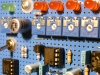
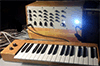
For my keyboard (look left ) I used a shift register to detect the keys pressed, I can do that because my keyboard has just 32 keys which is 4x a byte so I use a 32 bit word uint32_t like this:
| Code: |
uint32_t create_key_array (void)
//get the pressed key, just all keys
{
uint32_t all_keys_pressed;
all_keys_pressed = 0;
PORTC = 0xF8;
uint8_t read_the_keys;
for (uint8_t rowcounter=0x00; rowcounter<0x08; rowcounter++)
{
_delay_us(20);
read_the_keys = PIND;
if (bit_is_set(read_the_keys, 4)) {all_keys_pressed|=(1UL<<rowcounter);}// for shifting a 32 bit word use 1UL
if (bit_is_set(read_the_keys, 5)) {all_keys_pressed|=(1UL<<(rowcounter + 8));}
if (bit_is_set(read_the_keys, 6)) {all_keys_pressed|=(1UL<<(rowcounter + 16));}
if (bit_is_set(read_the_keys, 7)) {all_keys_pressed|=(1UL<<(rowcounter + 24));}
PORTC++;
}
return all_keys_pressed;//32 bits number, each bit represents a key
} |
The fun in this is that by looking at all_keys_pressed and check if it is 0, no key is pressed.
If all_keys_pressed is not 0, just shift and check which key is pressed.
I don't know if this is the most elegant way, but it works for me...
_________________
my synth |
|
|
Back to top
|
|
|
floating-water
Joined: Oct 06, 2020
Posts: 62
Location: UK
|
| Posted: Wed Nov 18, 2020 9:16 am Post subject:
|
|
|
Caught your youtube channel, your synth sounds p.h.a.t and I love your compositional style you could score an ominous, quirky british TV show with your setup I reckon. How one earth you build a vocoder?
Anyway ye so you absolutely lost me at 32 keys; so whats happening here. Do you have your keyboard being scanned by a cpu/arduino first or is this void of all that? How does CV get generated? Am I asking the wrong questions |
|
|
Back to top
|
|
|
Grumble
Joined: Nov 23, 2015
Posts: 1320
Location: Netherlands
Audio files: 30
|
|
|
Back to top
|
|
|
floating-water
Joined: Oct 06, 2020
Posts: 62
Location: UK
|
| Posted: Sat Dec 12, 2020 7:34 pm Post subject:
|
|
|
When I tried compiling the sketch it gave an error:
'scanColumn' was not declared in this scope
on this bit:
| Code: | void loop()
{
for (int colCtr = 0; colCtr < NUM_COLS; ++colCtr)
{
//scan next column
scanColumn(colCtr); |
What on earth does that mean? |
|
|
Back to top
|
|
|
|

 Forum index » DIY Hardware and Software » Musical Interfaces

