| Author |
Message |
Inventor
Stream Operator

Joined: Oct 13, 2007
Posts: 6221
Location: near Austin, Tx, USA
Audio files: 267
|
 Posted: Thu May 11, 2017 10:08 pm Post subject:
My Maker Hobby Posted: Thu May 11, 2017 10:08 pm Post subject:
My Maker Hobby
Subject description: ...and other fun stuff... |
  |
|
Imagine no computer, no internet, no programming, no money either. Well maybe just a hint of money. How could you make electronic music? Stang (Stan Lunetta) showed us how - use CMOS chips, glue them to copper sheets, and solder them together with wires. It's a simple, highly cost effective idea that works.
That is the appeal of the Lunetta I guess - the simplicity of it, the nostalgia, the legacy of a poor man doing brilliant things. I want to do similar work but with a bit more simplicity for the end user. Lots of people want digital synths but they have things called lives. You know: work, kids, family, mortgage, car payments, the complexity of life. There is no time to school up on CMOS. So how can we better serve this audience?
That's the point of this thread. Stay tuned or better yet join in and we'll have a conversation about how to innovate in the tradition of Stang!
Les
p.s. Important Note: the contents of this thread are protected by the share-alike non-commercial version of the Creative Commons open source license. You can read up on it here:
https://creativecommons.org/licenses/by-nc-sa/4.0/
_________________
"Let's make noise for peace." - Kijjaz
Last edited by Inventor on Mon May 15, 2017 1:56 pm; edited 3 times in total |
|
|
Back to top
|
|
 |
Inventor
Stream Operator
Joined: Oct 13, 2007
Posts: 6221
Location: near Austin, Tx, USA
Audio files: 267
|
| Posted: Sat May 13, 2017 5:02 am Post subject:
|
|
|
On my desk is a flickering red light - two of them actually. Two LEDs pointed at each other forming what is essentially a bidirectional optical interconnection node. It was last night's project and for a change I went slowly and patiently and it works just fine now.
What is it? It's a music maker based on an oscillating pair of LEDs. I'll get into the details in another post later in this thread, suffice to say it will become a simple and affordable little music source that NoodleDriver and I will open source for noncommercial use (contact us for permission to use commercially).
I envision a novel approach to audio done this way, with optical interconnect guided by light tubes. Again the idea is to make electronics easy - no soldering, no datasheets (or simple ones in their place), and an easy finger-safe way to hook things up that really dazzles!
So read on and I'll explain how it works. It's easy, you'll see!
praise His holy name
Les
_________________
"Let's make noise for peace." - Kijjaz |
|
|
Back to top
|
|
|
Inventor
Stream Operator
Joined: Oct 13, 2007
Posts: 6221
Location: near Austin, Tx, USA
Audio files: 267
|
| Posted: Sat May 13, 2017 6:21 am Post subject:
|
|
|
OK! Time to divulge some secrets! Ears on, eyes open, and brain going kathunka-whir everyone, here goes something...
The biggest secret that I drew from the work of others to create this sort of audio rate optical interconnect may be found at this web page:
https://playground.arduino.cc/Learning/LEDSensor
There you can study - to whatever level of depth you wish - how to use an LED in reverse as a light sensor! Yeah, it's true: it's actually possible to detect light with an LED and all it takes is the LED, a 100 Ohm resistor, and two digital pins of an Arduino micro-controller. Of course we can use photodiodes or the more familiar CdS cell (LDR), but to get super low cost and bidirectional communication this is the trick.
If you study up on the example program provided on that page you will learn that the code first detects light with the LED in reverse bias, then drives emitted light out of the LED in forward bias. The duration of the driven light can be set proportional to the duration of the sensing with a simple change to the code, thus converting the detected light level into a time duration. Further, since the process repeats ad infinitum in a loop, this time duration becomes an audio rate frequency.
So what I did was make two of these devices and point their LED's at each other. The code involved is almost entirely the stock example code, plus a programmer code and an Arduino UNO board to act as programmer. Oh, and I almost forgot to mention that the micro-controller I'm using is an ATtiny84.
Any ATtiny chip will do I suppose, but the ATtiny84 is a 14 pin DIP chip so that there are 11 I/O pins. The smaller ATtiny85 is a dollar or so less expensive at $2 typical price, however it has only 5 (technically 6 but in typical use 5) pins. Either works well and there is a host of other ATTiny chips available.
So there you go, the ingredients of the special sauce for audio rate optical interconnect are yours now! Mix up a batch of wholesome goodness of your own today!
Les
praise His holy name!
_________________
"Let's make noise for peace." - Kijjaz |
|
|
Back to top
|
|
|
Inventor
Stream Operator
Joined: Oct 13, 2007
Posts: 6221
Location: near Austin, Tx, USA
Audio files: 267
|
| Posted: Sun May 14, 2017 12:32 am Post subject:
|
|
|
Hah! I had to laugh when I figured out this technique of landing a quadcopter, or a UFO for that matter, at night. Laugh, laugh if you wish - have a good laugh - but it's true and I'll show you how. But first a couple of photographs to get you up to speed with things.
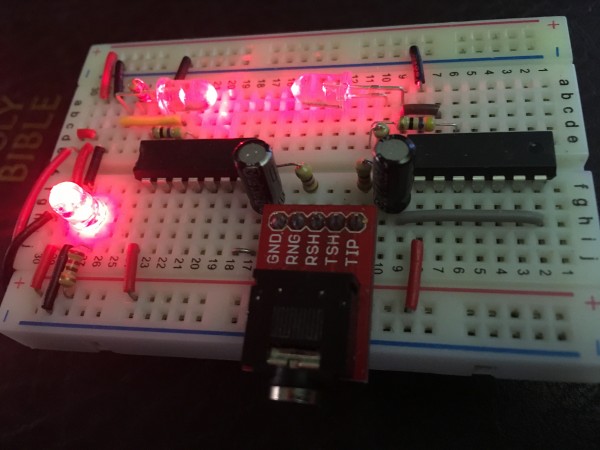
I had trouble getting my images across the web from phone to computer, so they are a bit delayed. Attached you will find the Optical Oscillator photo. at the top of the image you see two red LEDs with leads bent and installed such that they face each other. These are attached to two chips. The chips are programmed to read a light level by putting the LEDs into reverse biased mode (photodiode mode), and then they are forward biased for an amount of time proportional to the measured brightness, thus converting the brightness into a frequency.
by placing these two in proximity of each other and facing together, they synch up and become an oscillator. Rotating one such that the light coupling is reduced causes the oscillation frequency to decrease. This makes for some fun with audio optics, and that is just one connection. Imagine now a panel of such devices, each with four or more LEDs all connected somehow... Such things are possible and even at a low price due to the ubiquitous (love that word) nature of the humble LED.
So get yourself some LEDs, some ATtiny84 chips, and have some fun!
Les
Earth has no sorrow that Heaven can't heal.
| Description: |
|
| Filesize: |
1.76 MB |
| Viewed: |
745 Time(s) |
| This image has been reduced to fit the page. Click on it to enlarge. |
|
_________________
"Let's make noise for peace." - Kijjaz |
|
|
Back to top
|
|
|
Inventor
Stream Operator
Joined: Oct 13, 2007
Posts: 6221
Location: near Austin, Tx, USA
Audio files: 267
|
| Posted: Sun May 14, 2017 3:27 am Post subject:
|
|
|
Alright, as promised I think that just maybe there is an optical way to steer a quadcopter in close proximity to the ground. This technique does not rely on accelerometers or gyros, just a single axis compass and four LEDs driven by an Arduino (ATtiny84). It works as follows.
You connect the four LEDs using eight pins and drive them at independent self-oscillating frequencies. This is done with the provided example program modified to work with four LEDs. The LEDs are mounted on the four corners of the craft, and I'm not certain but I believe they must be pointed outwards instead of straight down, but probably straight down will work also. Anyway, here's more.
The LED will oscillate slower when it sees it's own reflection brighter in the example program. This behavior must be modified into a PWM for motor control that runs faster when the light is brighter. OK, Now let's say that the craft is fully horizontal. Each LED has been calibrated to PWM at say 50% duty cycle and the motors hover.
Next the craft drifts or we disturb the craft, pushing it from above on one corner. That corner is now lower, so the distance to the ground is less and the light seen is brighter. This speeds up the duty cycle of the motor control and the motor spins faster and that corner goes up.
When the corner is raised, the light is dimmer, the PWM gets lower and the motor slows down. This hovers the craft a certain distance above the ground. Now it isn't quite that simple because the craft can drift sideways, and also the behavior of the PWM response must be dampened or modeled by a PID equation (Proportional Integration Differentiation).
So there's more to it and it will take some study but for the right situation it may actually work. For example if the craft is located in a valley or bowl shaped space, then as the craft drifts to the edge of the bowl, it will tilt up with the bowl and correct itself toward the middle.
Well, you get the idea. As usual the basis of a concept is naturally not fully developed. Still, you can see how something like this could really work as part of a system. It can be done with a camera as well and possibly a ring of light, with the camera detecting ovalness in the shape of the projected light ring.
Also it is easy enough to place a convex-convex lens over the LEDs to extend their range. I like doing that, you can make an LED beam half way across a room with a simple lens held above it. 
That's all, time to experiment!
Les
praise His holy name
_________________
"Let's make noise for peace." - Kijjaz |
|
|
Back to top
|
|
|
sonic

Joined: Dec 02, 2010
Posts: 106
Location: Victoria BC
|
| Posted: Sun May 14, 2017 8:36 am Post subject:
|
|
|
This is intriguing stuff Les. I'm ordering some ATTiny chips so I can join in the fun.  |
|
|
Back to top
|
|
|
mosc
Site Admin

Joined: Jan 31, 2003
Posts: 18251
Location: Durham, NC
Audio files: 226
G2 patch files: 60
|
| Posted: Sun May 14, 2017 2:01 pm Post subject:
|
|
|
Les, I learned a lot by reading your post. You are very creative and you're always thinking.

_________________
--Howard
my music and other stuff |
|
|
Back to top
|
|
|
LFLab
Joined: Dec 17, 2009
Posts: 497
Location: Rosmalen, Netherlands
|
| Posted: Sun May 14, 2017 2:17 pm Post subject:
|
|
|
I believe there was a schematic in Elektor which used this effect, don't recall where or how, and there are a lot of projects in their 50-odd years of existence 
I believe there are some other parts which can be abused to generate a photoelectric response, bipolar transistors? |
|
|
Back to top
|
|
|
Grumble

Joined: Nov 23, 2015
Posts: 1318
Location: Netherlands
Audio files: 30
|
| Posted: Sun May 14, 2017 2:25 pm Post subject:
|
|
|
A nice little experiment:
Connect an LED to a probe of an oscilloscope and point the LED to the trace of the scope.
Watch the effect of photoelectric voltage produced bij the LED  |
|
|
Back to top
|
|
|
Inventor
Stream Operator
Joined: Oct 13, 2007
Posts: 6221
Location: near Austin, Tx, USA
Audio files: 267
|
| Posted: Mon May 15, 2017 12:15 am Post subject:
|
|
|
Oh, how encouraging it is to read your responses! I've been working on this stuff for days now and I've had fun so far. It has also brought to focus some interesting observations. Like I work harder not smarter - gotta turn that around! I tend to have great ideas and spotty implementation at best, so there is definitely room for improvement.
I got the quadcopter thing t act "kind of" right. It's a qualified success though because of a limitation of the ATtiny libraries. They don't do threading (or at least the one I chose doesn't), so I have spent hours and hours wasted when I realize just now typing this out that I can use an UNO!
** correction: it is a Due that has threading, not an UNO **
Well, that is next - also the optical interconnect works great for control signals, but it's too slow for audio. That's good to know. Back to it!
Les
p.s. i appreciate your continued support!
_________________
"Let's make noise for peace." - Kijjaz
Last edited by Inventor on Mon May 15, 2017 1:58 pm; edited 1 time in total |
|
|
Back to top
|
|
|
Inventor
Stream Operator
Joined: Oct 13, 2007
Posts: 6221
Location: near Austin, Tx, USA
Audio files: 267
|
| Posted: Mon May 15, 2017 4:27 am Post subject:
|
|
|
Correction: even an UNO does not do threading, its a Due. I transferred the circuit to the programmer UNO because it has tone() and can make square wave tones (well one, varying in frequency). After a little fiddling around I soon got it working and the results are quite pleasant. it now makes computery blip-streams that I really enjoy.
I know nobody is impressed with blinky lights and blippy sounds, its just that I have not done this sort of thing for quite a few years and it's a very nostalgic experience. I uses to spend hours rolling into days and weeks breadboarding music circuits like this.
Next up I want to 3D print something perhaps, though I don't have much in the way of filament. I do have a full spool of flex and two types of conductive filament. I said I would 3D print some circuits and then never did anything but get a good start. Maybe I should build upon that beginning next.
faster would be to 3D print breadboards of my own choosing in terms of connectivity. I have some scrap breadboards I can pull clips from to populate a printed breadboard plastic unit. Then I could breadboard a quadcopter mock-up and explore the optical quadcopter concept.
What do YOU think I should do next?
Les out,
praise the Lord!
_________________
"Let's make noise for peace." - Kijjaz |
|
|
Back to top
|
|
|
Inventor
Stream Operator
Joined: Oct 13, 2007
Posts: 6221
Location: near Austin, Tx, USA
Audio files: 267
|
|
|
Back to top
|
|
|
Inventor
Stream Operator
Joined: Oct 13, 2007
Posts: 6221
Location: near Austin, Tx, USA
Audio files: 267
|
| Posted: Tue May 16, 2017 12:55 am Post subject:
|
|
|
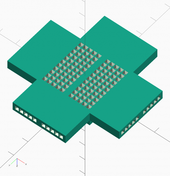
I've been making progress on my new emSynth project. It's the optical interconnect one. I've figured out how to make it do Fuzzy Logic which I studied just a little back in college. The concept is very simple and I can explain it in time.
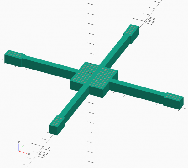
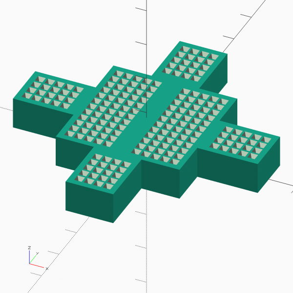
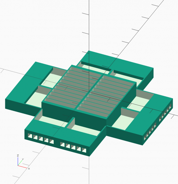
the images below show a custom breadboard design that I'm working on at the moment. The concept is to resuse the internal clips from old breadboards, placing them into a new plastic shell. This idea has been on my mind for quite some time now and it feels good to actually put it into practice.
Once built (and I am printing the first one as I write this), I will insert the clips and make a few modules. Actually now that I've made this design, I am thinking of a simpler way to make it. the difference is whether the four wings are printed horizontally or vertically like the rest of the design.
In the case shown, the goal is to make an initial foray into the realm of a fully three-dimensional breadboard, say like one wrapped around a cylinder or whatever. So it's an experiment as much as a prototype. Far simpler, I now realize I could have made those wings just like the rest of the breadboard, simply oriented at 90 degree angles. I may make both designs for comparison purposes.
Or basically if the first design does not turn out well, I have a backup plan. Either way it's a simple way to prototpe a small system!
Les
p.s. be sure to check out my 3D printed Music facebook page here: https://www.facebook.com/MusicIn3D/
| Description: |
|
| Filesize: |
45.14 KB |
| Viewed: |
580 Time(s) |
| This image has been reduced to fit the page. Click on it to enlarge. |
|
| Description: |
|
| Filesize: |
54.84 KB |
| Viewed: |
503 Time(s) |
| This image has been reduced to fit the page. Click on it to enlarge. |
|
_________________
"Let's make noise for peace." - Kijjaz |
|
|
Back to top
|
|
|
Inventor
Stream Operator
Joined: Oct 13, 2007
Posts: 6221
Location: near Austin, Tx, USA
Audio files: 267
|
|
|
Back to top
|
|
|
|

 Forum index » DIY Hardware and Software » Les Hall's Projects including eChucK