| Author |
Message |
PHOBoS

Joined: Jan 14, 2010
Posts: 5881
Location: Moon Base
Audio files: 709
|
 Posted: Sat Sep 23, 2017 6:48 am Post subject:
CMUSE Posted: Sat Sep 23, 2017 6:48 am Post subject:
CMUSE
Subject description: CMOS Triadex Muse (not tested) |
  |
|
a few weeks ago AlanP posted this link to a javascript version of the Triadex Muse in the chatroom.
I immediately thought that it wouldn't be too hard to recreate with a handfull of CMOS chips and
after a couple of days I couldn't resist the urge any longer and started drawing up a schematic.
I made use of this blockdiagram, the user manual and the programming manual. I also tested this
windows version. To get the timing correct I actually watched some demo videos frame by frame as
both the javascript and windows versions aren't 100% true to the actual muse. But I've also noticed
that there seemed to be a difference between muses (they also have different colored lights).
On to the circuit..
The original muse has 1 switch for both auto and step mode. you could actually use a toggle switch that
returns to it's center position from one side but they can be a bit harder to come by so I added a seperate
step button instead. I didn't add a debouce circuit so if you would use it as it is it'll probably be all over the
place. I also used a seperate reset switch (an external signal could be used as well) and if you add the
inverter and diode it will also stop the oscillator. The C 1/2 output is inverted which I found out after watching
some videos. C1, C2, C4, C8 are just divisions of the CLK frequency. For the odd divisions C3, C6 an XOR
gate is used and it is based on the examples found here.
The other part of the control circuit is a large shifregister made by chaining a couple smaller ones. The data
input bit is selected with switches W, X, Y Z which are connected to a parity generator made with 3 XOR gates.
If there is an even number of 1's selected with the switches the output will be 0 if there is an odd number of
1's it will be 1. (I think this was incorrect in either the javascript or windows version). This combination of
shiftregisters and XOR gates actually foms a LFSR which could create some pretty long sequences.
In the original muse the outputs from switches A, B, C, D are connected to a DAC which is used to control a
VCO. Getting the tuning right could be rather tricky so I went for a different, full CMOS, method instead which
is starting with a very high frequency and dividing it down to get the correct notes. The same way I made the
Chromatic Melody Generator. Switch D is used to select the octave (0 = one octave lower) which is done with U10b.
One thing that I haven't fully figured out yet is how the rest switch on the Muse functions. In the manual it says
it replaces the lowest note with a pause but I am not sure if the lowest note is just the low C or the output of
switch A or actually the lowest note in the sequence. Although I think that would be rather hard to implement.
I guess I could check the javascript and windows versions to see what they do.
I am not intending to actually built it although it is tempting. But besides the long shiftregister I pretty much have
all the components already in my current lunetta system so I could patch up something similar. If you do plan on
making one you'll probably won't be able to get 40 position slide switches and I think the best substitute would be
2x40 pin headers in combination with jumpers. Of course you could also adjust the number of dividers and shift-
registers. I was actually thinking about making a mini-cmuse.
| Description: |
|
| Filesize: |
166.94 KB |
| Viewed: |
1034 Time(s) |
| This image has been reduced to fit the page. Click on it to enlarge. |
|
_________________
"My perf, it's full of holes!"
http://phobos.000space.com/
SoundCloud BandCamp MixCloud Stickney Synthyards Captain Collider Twitch YouTube
Last edited by PHOBoS on Fri Mar 02, 2018 8:02 pm; edited 3 times in total |
|
|
Back to top
|
|
 |
blue hell
Site Admin

Joined: Apr 03, 2004
Posts: 24499
Location: The Netherlands, Enschede
Audio files: 298
G2 patch files: 320
|
| Posted: Sat Sep 23, 2017 7:30 am Post subject:
|
|
|

Great you figured it all out PHOBoS! This one I do understand at least.
_________________
Jan
also .. could someone please turn down the thermostat a bit.
 |
|
|
Back to top
|
|
|
blue hell
Site Admin
Joined: Apr 03, 2004
Posts: 24499
Location: The Netherlands, Enschede
Audio files: 298
G2 patch files: 320
|
| Posted: Sun Sep 24, 2017 7:59 am Post subject:
|
|
|
Re. the parity generator, odd parity seems more interesting than even parity, I've added an inversion for that after the xors.
Otherwise:
When the W, X, Y, Z switches are all switched to a position beyond the divider signals, and the shift register holds all zeros the xor yields a zero too - meaning the shifter state never changes.
Maybe this is the case for the original .. but I've found things to be a bit more interesting with the inverter added.
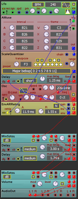
Now I need to figure out a good way to generate an output signal - I've implemented the thing as a controller, that is, it has no oscillator of it's own but just the weighted outputs of switch_a .. d summed (a DAC, say, or an R2R ladder).
Current code:
[Edit : spot the bugs :-)
I've changed things a bit since ... fixed the bugs, added a fifth interval selector, added div 5 and div 7 and added two external inputs going to the switches - so the switches now have 44 positions. Also added modulation inputs to each switch, decided to just keep the DA converter, that' s why I added switch E, to have 32 distinct output values, which seems plenty (using it with an external quantizer to make the actual note values)]
| Code: | interface
TModAmuse = class( TMod)
strict private
const
i_reset = 0;
i_trig = 1;
i_sela = 2;
i_selb = 3;
i_selc = 4;
i_seld = 5;
i_selw = 6;
i_selx = 7;
i_sely = 8;
i_selz = 9;
const
o_out = 0;
private
FOldRes : Boolean;
FOldTrig : Boolean;
FCountC1 : Integer;
FCountC2 : Integer;
FCountC3 : Integer;
FCountC4 : Integer;
FCountC6 : Integer;
FCountC8 : Integer;
FShifter : Cardinal;
FMemoryC1 : Boolean;
FMemoryC2 : Boolean;
FMemoryC3 : Boolean;
FMemoryC4 : Boolean;
FMemoryC6 : Boolean;
FMemoryC8 : Boolean;
public
procedure CreateIO; override;
procedure DoSlowTick; override;
end;
implementation
function SignalToLogic( const aValue: TSignal): Boolean; inline;
begin
Result := aValue > 0;
end;
function DecToZeroWithResetValue( var aValue: Integer; aResetValue: Integer): Boolean; inline;
begin
Result := False;
if aValue > 1
then Dec( aValue)
else begin
aValue := aResetValue;
Result := True;
end;
end;
function DecToZeroWithResetValueToggle( var aValue : Integer; var Memory: Boolean; aResetValue: Integer): Boolean; inline;
begin
if DecToZeroWithResetValue( aValue, aResetValue)
then Memory := not Memory;
Result := Memory;
end;
{ ========
TModAmuse = class( TMod)
}
procedure TModAmuse.CreateIO; // override;
begin
FIsSlow := True;
AddInput ( i_reset, 'reset');
AddInput ( i_trig , 'trig');
AddInput ( i_sela , 'sela');
AddInput ( i_selb , 'selb');
AddInput ( i_selc , 'selc');
AddInput ( i_seld , 'seld');
AddInput ( i_selw , 'selw');
AddInput ( i_selx , 'selx');
AddInput ( i_sely , 'sely');
AddInput ( i_selz , 'selz');
AddOutput( o_out , 'out' );
end;
procedure TModAmuse.DoSlowTick; // override;
function Select( aPos: Integer): Boolean;
begin
case aPos of
1 : Result := True;
2 : Result := FOldTrig;
3 : Result := FMemoryC1;
4 : Result := FMemoryC2;
5 : Result := FMemoryC4;
6 : Result := FMemoryC8;
7 : Result := FMemoryC3;
8 : Result := FMemoryC6;
9 : Result := ( FShifter and ( 1 shl 0)) <> 0;
10 : Result := ( FShifter and ( 1 shl 1)) <> 0;
11 : Result := ( FShifter and ( 1 shl 2)) <> 0;
12 : Result := ( FShifter and ( 1 shl 3)) <> 0;
13 : Result := ( FShifter and ( 1 shl 4)) <> 0;
14 : Result := ( FShifter and ( 1 shl 5)) <> 0;
15 : Result := ( FShifter and ( 1 shl 6)) <> 0;
16 : Result := ( FShifter and ( 1 shl 7)) <> 0;
17 : Result := ( FShifter and ( 1 shl 8)) <> 0;
18 : Result := ( FShifter and ( 1 shl 9)) <> 0;
19 : Result := ( FShifter and ( 1 shl 10)) <> 0;
20 : Result := ( FShifter and ( 1 shl 11)) <> 0;
21 : Result := ( FShifter and ( 1 shl 12)) <> 0;
22 : Result := ( FShifter and ( 1 shl 13)) <> 0;
23 : Result := ( FShifter and ( 1 shl 14)) <> 0;
24 : Result := ( FShifter and ( 1 shl 15)) <> 0;
25 : Result := ( FShifter and ( 1 shl 16)) <> 0;
26 : Result := ( FShifter and ( 1 shl 17)) <> 0;
27 : Result := ( FShifter and ( 1 shl 18)) <> 0;
28 : Result := ( FShifter and ( 1 shl 19)) <> 0;
29 : Result := ( FShifter and ( 1 shl 20)) <> 0;
30 : Result := ( FShifter and ( 1 shl 21)) <> 0;
31 : Result := ( FShifter and ( 1 shl 22)) <> 0;
32 : Result := ( FShifter and ( 1 shl 23)) <> 0;
33 : Result := ( FShifter and ( 1 shl 24)) <> 0;
34 : Result := ( FShifter and ( 1 shl 25)) <> 0;
35 : Result := ( FShifter and ( 1 shl 26)) <> 0;
36 : Result := ( FShifter and ( 1 shl 27)) <> 0;
37 : Result := ( FShifter and ( 1 shl 28)) <> 0;
38 : Result := ( FShifter and ( 1 shl 29)) <> 0;
39 : Result := ( FShifter and ( 1 shl 30)) <> 0;
else Result := False;
end;
end;
var
Swa : Boolean;
Swb : Boolean;
Swc : Boolean;
Swd : Boolean;
Data : Boolean;
Trig : Boolean;
Reset : Boolean;
begin
Reset := SignalToLogic( FInputs[ i_reset]);
Trig := SignalToLogic( FInputs[ i_trig ]);
if ( Reset and not FOldRes) or ResetFlag
then begin
ResetFlag := False;
FCountC1 := 1; FMemoryC1 := False;
FCountC2 := 2; FMemoryC2 := False;
FCountC4 := 4; FMemoryC4 := False;
FCountC8 := 8; FMemoryC8 := False;
FCountC3 := 3; FMemoryC3 := False;
FCountC6 := 6; FMemoryC6 := False;
FShifter := 0;
end;
if Trig and not FOldTrig
then begin
Data :=
Select( Round( FInputs[ i_selw])) xor
Select( Round( FInputs[ i_selx])) xor
Select( Round( FInputs[ i_sely])) xor
Select( Round( FInputs[ i_selz]));
DecToZeroWithResetValueToggle( FCountC1, FMemoryC1, 1);
DecToZeroWithResetValueToggle( FCountC2, FMemoryC2, 2);
DecToZeroWithResetValueToggle( FCountC4, FMemoryC1, 4);
DecToZeroWithResetValueToggle( FCountC8, FMemoryC2, 8);
DecToZeroWithResetValueToggle( FCountC3, FMemoryC1, 3);
DecToZeroWithResetValueToggle( FCountC6, FMemoryC2, 6);
FShifter := ( FShifter shl 1) + Cardinal( Ord( not Data));
end;
Swa := Select( Round( FInputs[ i_sela]));
Swb := Select( Round( FInputs[ i_selb]));
Swc := Select( Round( FInputs[ i_selc]));
Swd := Select( Round( FInputs[ i_seld]));
FOutputs[ o_out] := ( Ord( Swa) + 2 * Ord( Swb) + 4 * Ord( Swc) + 8 * Ord( Swd)) / 16.0;
FOldRes := Reset;
FOldTrig := Trig;
end;
|
_________________
Jan
also .. could someone please turn down the thermostat a bit.
|
|
|
Back to top
|
|
|
Steveg

Joined: Apr 23, 2015
Posts: 184
Location: Perth, Australia
|
| Posted: Fri Mar 02, 2018 5:28 pm Post subject:
|
|
|
Wow, I totally missed this post for months.
I had a read of the Muse programmers manual and I noticed a couple of things.
Blue Hell's intuition about odd parity is correct. At the bottom of page 2 it explicitly says that when all the theme slides produce 0's a one is clocked in.
In the section on tempo at the bottom of page 7 it says the tempo is doubled when you use the C1/2 setting on the sliders. This suggests the the raw oscillator is presented as C1/2 and then divided by two for the master clock C.
The description near the top of page 2 concerning note generation clearly talks about dividers so your implementation is clearly in keeping with the original. |
|
|
Back to top
|
|
|
PHOBoS
Joined: Jan 14, 2010
Posts: 5881
Location: Moon Base
Audio files: 709
|
| Posted: Fri Mar 02, 2018 7:48 pm Post subject:
|
|
|
| Steveg wrote: | | At the bottom of page 2 it explicitly says that when all the theme slides produce 0's a one is clocked in. |
If I am reading it correct it seems the programming manual is actually contradicting itself.
at the bottom of page 2 it does indeed say:
| Quote: | | Since all Theme slides had a zero on them prior to the first beat and no ones is an even number, a one was shifted in. |
however on page 1 it says:
| Quote: | | If the four Theme slides have an even number of ones on them (i.e. 0, 2, or 4), then a zero is introduced into the first bit of the shift register at the next tempo beat. |
In the end it doesn't really matter of course, it's just meant to be used as inspiration and if anyone would
actually like to built it they can choose whatever they prefer or even add a switch for both options. (add
another XOR gate and you can even control it with a signal).
_________________
"My perf, it's full of holes!"
http://phobos.000space.com/
SoundCloud BandCamp MixCloud Stickney Synthyards Captain Collider Twitch YouTube |
|
|
Back to top
|
|
|
blue hell
Site Admin
Joined: Apr 03, 2004
Posts: 24499
Location: The Netherlands, Enschede
Audio files: 298
G2 patch files: 320
|
| Posted: Fri Mar 02, 2018 8:06 pm Post subject:
|
|
|
| PHOBoS wrote: | (add
another XOR gate and you can even control it with a signal). |
Ain't logic great eh ... a lot of control on this ting indeed is more XORs
_________________
Jan
also .. could someone please turn down the thermostat a bit.
|
|
|
Back to top
|
|
|
Steveg
Joined: Apr 23, 2015
Posts: 184
Location: Perth, Australia
|
| Posted: Fri Mar 02, 2018 8:26 pm Post subject:
|
|
|
The chiptunes circuits by Synaesthesia and others interest me and this circuit as well as the related Psych Tone circuit touch an itch I am trying to scratch. But I want something that can develop melodic sequences and then elaborate on them rather than spewing out random tones.
I've been thinking about a set of 4 x 8 bit latches that hold a sequence of 8 notes that can be scanned by a 4051 clocked at the note tempo. This gives a repeating 8 note motif. It should be possible to set up a table of key changes and other variations that are periodically used to update the latches with new motifs. It is a job better done in software than hardware I think. At least until the concept is developed enough to simplify the structures and mutations. |
|
|
Back to top
|
|
|
Steveg
Joined: Apr 23, 2015
Posts: 184
Location: Perth, Australia
|
| Posted: Fri Mar 02, 2018 8:29 pm Post subject:
|
|
|
| PHOBoS wrote: |
however on page 1 it says:
|
So it does ... I missed that. Carry on then. |
|
|
Back to top
|
|
|
PHOBoS
Joined: Jan 14, 2010
Posts: 5881
Location: Moon Base
Audio files: 709
|
| Posted: Fri Mar 02, 2018 8:54 pm Post subject:
|
|
|
Evolving melodies is something I am interested into as well. Basically I want something to make music for me that
actually sounds musical (and what I really would like is to have it controlled with sensors so its mood depends on the
weather). It's what got me into this whole synth building thing. My current patch is set up in a way that it somewhat
creates 'songs' that partially flow into eachother. There is a shiftregister in there that creates sequences which are
repeated for a while before loading it (randomly) with different data. The output is fed into an R2R which is fed into
my Braids module which has a build in quantizer. I ran out of patchcables but it should be possible to double up on
these sequencers and mix them together to create different note sets. I do agree that something like this is easier
to accomplish with software, and midi might be very useful for it too. When I had just joined here I actually used a
PIC for a similar concept.
I case you missed it you might want to take a look at Top Top's Melody Oracle and latest additions to it.
oh and also: CMOS Psych Tone Tune Computer
_________________
"My perf, it's full of holes!"
http://phobos.000space.com/
SoundCloud BandCamp MixCloud Stickney Synthyards Captain Collider Twitch YouTube |
|
|
Back to top
|
|
|
PHOBoS
Joined: Jan 14, 2010
Posts: 5881
Location: Moon Base
Audio files: 709
|
| Posted: Fri Mar 02, 2018 9:14 pm Post subject:
|
|
|
On a side note that also reminds me again that I want to make some kind of bit shuffler/rotator for my Chromatic Melody Generator.
It uses 4 bits to select a note (+ 3 bits for octave selection) and I think it could be interesting to test what the same control sequences
would produce if you connect them to the inputs differently. If I am not mistaken there are 24 unique combinations. (so each output
from a sequence only connected to one input) I actually did start on a design for it once, which I think uses a bunch of muxes.
Synaesthesia might have done something like that too.
_________________
"My perf, it's full of holes!"
http://phobos.000space.com/
SoundCloud BandCamp MixCloud Stickney Synthyards Captain Collider Twitch YouTube |
|
|
Back to top
|
|
|
blue hell
Site Admin
Joined: Apr 03, 2004
Posts: 24499
Location: The Netherlands, Enschede
Audio files: 298
G2 patch files: 320
|
| Posted: Fri Mar 02, 2018 9:32 pm Post subject:
|
|
|
I use arp thingies a lot to grab from sequences ... those clock data in on an input clock and sort it (low to high, high to low, in sequence, reversed, input filtering it too .. on like changed value, or always) and clock it out on an output clock .. a software thing to do yes ... also using a poetry generator .. which picks occurred sequences and determines what to do next from that, software too ..
I like to call those things 'listeners' as I think that is what makes them interesting .. to listen to input and output it in some warped way.
Envelope followers and pitch detectors would qualify as well. The idea is to have a patch and then some listeners inside of it peeking into it and do some stuff related to what they hear.
Some stuff could be analog,some stuff could be discrete logic some stuff would need a computer. The idea of a patch listening to itself is intriguing to me, and it seems to help into evolving stuff .. especially when the response is being delayed in time .. and/or when it is being applied recursively.
_________________
Jan
also .. could someone please turn down the thermostat a bit.
|
|
|
Back to top
|
|
|
blue hell
Site Admin
Joined: Apr 03, 2004
Posts: 24499
Location: The Netherlands, Enschede
Audio files: 298
G2 patch files: 320
|
| Posted: Fri Mar 02, 2018 9:45 pm Post subject:
|
|
|
Re. PHOBos latest post .. shifted sequences are fun .. like when you have an eight step sequencer .. give it an output that i delayed by some some steps.
Or when you have a 16 step one where you ,, say .. eight ... use steps 4 - 11 on a separate output .. this is something I do (easily) in software .. but with some muxes and logic should be doable in hardware .. and it is nice to have a lil overlap in the sequences and some difference too in a canon like sequence.
Also .. then comes in the M A N IA C subject ... with reversal of sequences, inversions of sequences, disabling steps repetition of steps, setting lengths for steps etc.
_________________
Jan
also .. could someone please turn down the thermostat a bit.
|
|
|
Back to top
|
|
|
Grumble

Joined: Nov 23, 2015
Posts: 1319
Location: Netherlands
Audio files: 30
|
| Posted: Sat Mar 03, 2018 12:20 am Post subject:
|
|
|
I did something similar as you discribe in my 16 step sequencer: it has a variable number of repeating steps (1 to 16), where the 16 potvalues go to one output and the last 8 potvalues go to the other output.
So if you set the number of steps between 1 and 8 you actualy have two parallel sequencers.
If you set the number of steps eg 16 you get:
output 1; 1, 2, 3, 4, 5, 6, 7, 8, 9, 10, 11, 12, 13, 14, 15, 16
output 2; 1, 2, 3, 4, 5, 6, 7, 8, 1, 2, 3, 4, 5, 6, 7, 8 etc
Since the sequencer has a cv controllable speed setting, you can use the first 8 potmeters for controlling a VCO and the second 8 potmeters for setting the speed of the sequencer.
_________________
my synth |
|
|
Back to top
|
|
|
Steveg
Joined: Apr 23, 2015
Posts: 184
Location: Perth, Australia
|
| Posted: Tue Mar 06, 2018 4:13 pm Post subject:
|
|
|
So I have thought about the tune generator, I considered a 7 note system but eventually selected a 5 note system based on a pentatonic scale but the architecture can be expanded to handle more notes. The idea is to have an 8 note sequence that can be played repeatedly in different keys while allowing notes to be substituted to generate new motifs. There are 4 modules
Note generator -> Note bank -> Key transposer -> tone generator.
The note generator creates a valid relative note. For the 7 or 12 note versions it needs to consider the previous and next notes from the note bank. For a pentatonic system it could be as simple as a 4017 and some diodes to select and encode a relative note from I to V.
The note bank holds a sequence of 8 relative notes and can read out those notes on the tempo. More complex banks can scan forwards and backwards. The simple version is 3 x 4015s and a 4053. The 4015s are clocked through on the tempo to read out a note and the 4053 allows the next note to come from the end of the register or be a new note from the note generator.
The key transposer takes the relative note from the note bank and applies a key selector to generate the absolute note to be played. It can clock in a new key at the end of any 8 note sequence. The note from the note bank is demuxed to a series of 4052s. Each 4052 takes a 2 bit key selector and the note valid line and creates a signal on one of N tone lines. One half of a 4052 is used for each possible note from the note bank. Something like a 4013 could be used to hold the key.
The tone generator take the absolute note from the key transposer and possibly any octave shifts and generates a tone that can be sent to speakers.
This tone can be coloured by any of the usual lunetta square wave mangling tricks. The generator could be implemented like PHOBoS' Chromatic Melody Generator.
You can drive all these various inputs from a variety of random inputs or you can build a top level melody controller that has a scheme allowing a repeating sequence of key changes and note substitutions to be applied to the other modules. With a consistent interface between each module new modules can be tried and substituted as required. |
|
|
Back to top
|
|
|
PHOBoS
Joined: Jan 14, 2010
Posts: 5881
Location: Moon Base
Audio files: 709
|
|
|
Back to top
|
|
|
Steveg
Joined: Apr 23, 2015
Posts: 184
Location: Perth, Australia
|
| Posted: Thu Mar 08, 2018 2:57 pm Post subject:
|
|
|
PHOBoS +1
Yes exactly for the simple version.
I also had a not connected forward/reverse input for interface consistency
and I present pins 5, 2 & 11 of each 4015 as the interface back to the note generator so a 7 note generator can decide on a better choice of new note.
Also NOR pin 2 of the 4015s, run it through a switch and OR it with NEW/OLD NOTE. The switch is labelled "autofill" (or similar) so that every time a rest is found it tries to replace it with a new note from the note generator. This makes the start up take off smoothly. And pin 5 is the correct pin to take the output from.  |
|
|
Back to top
|
|
|
Steveg
Joined: Apr 23, 2015
Posts: 184
Location: Perth, Australia
|
| Posted: Mon Jun 28, 2021 8:52 pm Post subject:
|
|
|
| In case anyone is interested, a Muse turns up in this video https://www.youtube.com/watch?v=cTCVm-Eo1F0 at 1:30 and a couple of times later. It is never mentioned but is obviously in use connected to Joseph Paradiso's giant modular synth. |
|
|
Back to top
|
|
|
PHOBoS
Joined: Jan 14, 2010
Posts: 5881
Location: Moon Base
Audio files: 709
|
|
|
Back to top
|
|
|
Steveg
Joined: Apr 23, 2015
Posts: 184
Location: Perth, Australia
|
| Posted: Tue Jun 29, 2021 8:43 pm Post subject:
|
|
|
This page has some pictures of the interface and Joe's discussion of his interface philosophy (section 5.5): http://paradiso.media.mit.edu/ModularSynthsVoltageConnect-17-ReallyFinal.pdf
"With the Triadex Muse (the world’s first autonomous
sequencer product) [72], I can, for example, voltage-control the
pitch and clock rate, inject an external clock, have access to all
bits coming from the sequencer into the note-generating
priority encoder, and inject external bits into the sequencer. As
the Muse was probably inspired by Marvin’s hobby of
improvising fugues at the piano [73], the Muse is all about
melody and does nothing with timbre, as it just produces a
square wave. When married to my modular, however, the
Muse becomes a timbre and melody monster, producing thick
waves of dynamically changing sound in accordance with state
determined by the current patch"
And this is a class project inspired by the muse: http://paradiso.media.mit.edu/MusicalStateMachine/index.html
There may be more stuff buried in corners under other titles as I no longer have the concentration to read everything but it is a worthwhile page: http://paradiso.media.mit.edu/synth.html |
|
|
Back to top
|
|
|
Steveg
Joined: Apr 23, 2015
Posts: 184
Location: Perth, Australia
|
| Posted: Thu Jul 01, 2021 7:37 am Post subject:
|
|
|
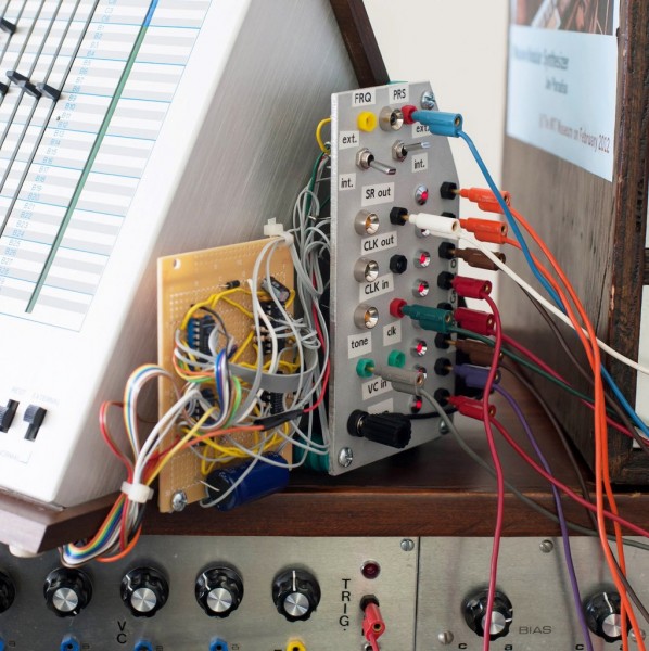
I sent a query to Professor Joe Paradiso and he sent me a nice response and permission to reproduce it here. There is a close up image of the Muse interface wich I will attach when I remember how  . Now over to Joe: . Now over to Joe:
Yes, the Muse is a wonderful box - An Eddie Jobson piece just shuffled on yesterday when I was driving, and he was one of the few popular artists who used it quite a bit - I’m looking forward to using the Muse in another piece soon.
Yes, I have written bits about what I’ve done with it, and you may have found them - you probably saw the blurb I wrote about the interface to the Muse in the 2017 paper I did for the Berklee conference: http://paradiso.media.mit.edu/ModularSynthsVoltageConnect-17-ReallyFinal.pdf - it’s on pg. 10, where I had that photo of the muse mod - quoting myself from back then: 'With the Triadex Muse (the world’s first autonomous sequencer product) [72], I can, for example, voltage-control the pitch and clock rate, inject an external clock, have access to all bits coming from the sequencer into the note-generating priority encoder, and inject external bits into the sequencer.’ I’ll include the photo of the interface below - indeed, it does all that - I can also inject my own clock if I want (the Muse provides for that), plus I have the Muse’s clock on a separate output - I can also not only VC the pitch, but also put my own master high-frequency clock in for that if I want, I believe (I think that’s what the yellow ‘FRQ’ jack is, but it’s been a while). I’ve got the 6 bits coming out of the selector switches that I can route into my modular, but I can also interrupt one of them and insert my own signal to mess a bit with the sequence (don’t remember exactly what I do there - but that switch on the upper right lets me put my own bit into the priority encoder stream as opposed to just let it default to one of the sliders). When I built the interface to it, I took some rough notes, but there’s no detailed ’schematic’ as such - as I never had a proper schematic for the Muse to begin with away from the high-level diagram in the patent (even though Marvin was a good friend, and I met with Ed Fredkin when I started working it - they couldn’t find one!).
When I use it, as you can see in the photo below (taken from the patch I did for a big event we ran at the Lab - described here - https://resenv.media.mit.edu/SynthMuse/) the Muse is pretty heavily wedded to the synth - the logic outputs change sequences and patch coding on the synth proper while I pump a digital output occasionally into the Muse to torque its sequence, and I sometimes slow/speed/stop the clock on the Muse, or use the Muse clock as the master clock to drive everything happening on the Modular, or drive the Muse with my own sequencer clock. The patch on that site (this is the best version) https://resenv.media.mit.edu/SynthMuse/SynthMeetsMuse-Ex-1.mp3 is very Muse - it’s making one of the main complex sequences that comes in and out, and I think I made other sequences myself out of the bits coming out of the Muse - I used lots of logic in the patch and it was pretty complex. |
|
|
Back to top
|
|
|
Steveg
Joined: Apr 23, 2015
Posts: 184
Location: Perth, Australia
|
| Posted: Thu Jul 01, 2021 7:38 am Post subject:
|
|
|
The audio from the Muse is that iconic square wave - Marvin was all about melody, but didn’t really get timbre as well. Hence I mess heavily with it in the modular, filtering it of course, sometimes driving PLLs to messily track the sound, but also going through logic modules to selectively fatten it up, adding echoes/reverbs/delays, and all the other tricks - the Muse audio output can be in a patch in many places and sound different when different audio signal paths come into the mix. These days, I’m starting to hear hum on it, so put it though a comparator to clean it up (I have those on the modular too) - I’m probably going to take it apart before long and replace the filter capacitors in the power supply. I kick myself a bit for not doing it when I had it open to make the mod… I sometimes think of paralleling the bits on the priority encoder into an D/A converter so I can get a proper control voltage out of it and directly voice other oscillators - but I can in principle do that anytime, as I’ve broken those bits out already via the black jacks at right on the panel.
In the patch I did for the Plasma Fusion Center, the main Muse apparition is that gurgling arpeggio that comes in periodically - you can hear that I stop the clock a fair amount to hold notes, and it goes through many signal processing chains that fade in and out, but the gurgling filter is the most obvious one you can hear. You can also hear how I throw bits into the Muse to change the sequence there. I’ve got a long excerpt of it on BandCamp - https://joeparadiso.bandcamp.com/track/alcator
Yes, I think there are some demo videos floating around that the students posted where I go through the Muse interface that I think you found, but I use the Muse on almost every patch since I did the mod - it’s heavily in this one that I did a year ago January - https://joeparadiso.bandcamp.com/track/h-nggerberg-redux - but to be honest, I don’t remember exactly what’s Muse and what’s other sequencers - they are heavily interconnected there.
This piece is essentially all Muse - https://joeparadiso.bandcamp.com/track/your-bleepiness - it’s driving all kinds of things on the Modular, but everything comes from the Muse here. Not the easiest thing to listen to, but there are a few different modes in it…
OK - thanks for the interest, and hope this sheds a bit of light on how I use the Muse in different ways - it will continue in work I do later this year as I’ve finished my new studio and will be doing more down there soon (busy now building a new module I thought up around a formant generator I had as a kid, and enjoying playing the keyboards again - the synth can’t have all that fun on its own!).
Best -Joe-
| Description: |
|
| Filesize: |
210.3 KB |
| Viewed: |
231 Time(s) |
| This image has been reduced to fit the page. Click on it to enlarge. |
|
|
|
|
Back to top
|
|
|
|

 Forum index » DIY Hardware and Software » Lunettas - circuits inspired by Stanley Lunetta