| Author |
Message |
bigtex

Joined: Mar 30, 2006
Posts: 323
Location: Cupertino, California
|
 Posted: Wed Apr 12, 2006 7:49 pm Post subject:
Analog Devices AD534JD multiplier Posted: Wed Apr 12, 2006 7:49 pm Post subject:
Analog Devices AD534JD multiplier
Subject description: from a "Duffing Oscillator Analog Chaos Demonstration Module" (???) |
  |
|
Don't surf eBay when you're reallly really tired.
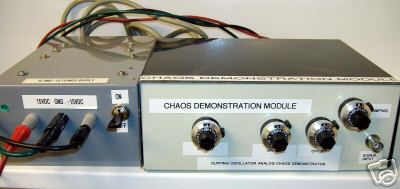
Let me elaborate. I won the following item:

Which was described as such:
"DUFFING OSCILLATOR ANALOG CHAOS DEMONSTRATION MODULE
Well ya got me this time. I have no idea what this is or what it does. Found this beauty at an amateur radio swap meet and it still works perfectly, said the seller. Great for testing communications circuitry or analog frequency response tests. has a great little +/-15 VDC differential power supply with it though. Smart buyers only!"
Okay. That's a really tantalizing description and picture. I guess I couldn't help myself. I really don't remember bidding on it (and I don't drink alcohol, either!) but at US $15, I guess it was worth it to find out...
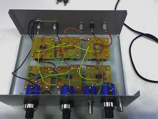
It arrived today, and didn't work (surprise!). I open it up and find out that it contains some of the ugliest soldering work I've ever seen (and I was a tech at a university... ugh... student soldering).
Behold:


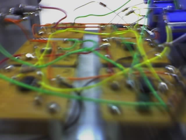
Okay. So the picture is blurry, but I think you can make out the really giant blobs or solder. Wow. On that second picture, you can also see a freely hanging resistor. Ah ha! The culprit. Well, maybe not. I tried touching the resistor to the only contacts it could have reached, and still got no output. Hrrmmmmm.....
But then I took a closer look and noticed some odd looking ICs with gold stickers on them. Turns out they are Analog Devices AD534JD chips, which according to Analog Devices are "having accuracy specifications previously found only in expensive hybrid or modular products."
I look these up on Digikey, and apparently they are rather expensive, at US $29.52 each (ouch!). Perhaps I should take this apart and use these expensive chips to make something much cooler. With a name like multiplier, I'm guessing a wave multiplier like the one seen here on Ken Stone's page could be in order.
Anybody have some outlandish ideas for circuits for me to use these chips in?
Maybe there wasn't actually any point to this post... I just thought some of you might be amused... but if you know of a really cool use for a multiplier, please do speak up!
Last edited by bigtex on Mon Sep 01, 2008 2:48 am; edited 2 times in total |
|
|
Back to top
|
|
 |
dnny

Joined: Mar 12, 2005
Posts: 519
Location: Helsinki, Finland
Audio files: 8
|
 Posted: Wed Apr 12, 2006 10:19 pm Post subject: Posted: Wed Apr 12, 2006 10:19 pm Post subject:
|
  |
|
nice one.
even if you will find that the chips are burned  you have got some nice 10turns pot´s and those very expensive 10turn knobs. is the power supply working correctly? you have got some nice 10turns pot´s and those very expensive 10turn knobs. is the power supply working correctly?
_________________
Association of experimental electronics
www.koelse.org
flickr: cable porn group |
|
|
Back to top
|
|
 |
bigtex

Joined: Mar 30, 2006
Posts: 323
Location: Cupertino, California
|
 Posted: Wed Apr 12, 2006 11:39 pm Post subject: Posted: Wed Apr 12, 2006 11:39 pm Post subject:
|
  |
|
Yeah! 3 x 20k and 1 x 5k Bourns 10 turn pots!! One of the fancy knobs is broken, though 
The power supply is good, or at least functional, though equally messy. But I can rebuild it. I have the technology. *cue $6M Man music*
It's got a 7815/7915 pair for +/-15v in it with HUGE heat sinks. So if I replace those with some higher current regulators, keep the nice big transformer and capacitors, I'll have a power supply to feed a nice big modular.... now I just need to build the modular...
All of my MusicFromOuterSpace boards arrived today! One SoundLab, one each of VCO, VCF, VCA, ADSR and a 16 step sequencer with a few extra analog boards. This is gonna be sweeeeeet. |
|
|
Back to top
|
|
 |
piedwagtail

Joined: Apr 15, 2006
Posts: 297
Location: shoreditch
Audio files: 3
|
 Posted: Sat Apr 15, 2006 6:37 am Post subject: Posted: Sat Apr 15, 2006 6:37 am Post subject:
|
  |
|
Purely empirical it would seem.
Looking at the datadiagram as posted and considering the transfer function:
You could simplify(i presume) by grounding the inputs x2 y2 z1 z2.
That changes the equation to Vo=A(x1*y1/sf).
Such that the input voltages x1 and y1 multiply and are divided by the stable reference.
You could try a vco into x1,an adsr into y1 and divide by an lfo into sf.
See what the scope says.
How A gain is manipulated i can't see.
My initial consideration is a rather bizarre wave mangler which would work in parallel with a clean wave channel and be mixed in with a controllable vca(or vactrol).
Looks fun albeit at that chip price you're the man to investigate!
Perhaps it can be G2'd?
Robert |
|
|
Back to top
|
|
 |
|

