| Author |
Message |
Freq Band

Joined: Sep 05, 2006
Posts: 57
Location: Los Angeles
|
 Posted: Tue Sep 12, 2006 6:27 pm Post subject:
Wilson VCO, Signal to Gate, Mixer - (w/pics) Posted: Tue Sep 12, 2006 6:27 pm Post subject:
Wilson VCO, Signal to Gate, Mixer - (w/pics)
Subject description: they work. but I had some Q's |
  |
|
From Ray Wilson's site:
Improved VCO:
http://www.musicfromouterspace.com/analogsynth/August2003VCO.html
Signal to Gate:
http://www.musicfromouterspace.com/analogsynth/signaltogate.html
Stereo Mixer:
http://www.musicfromouterspace.com/analogsynth/stereoinputmixer.html
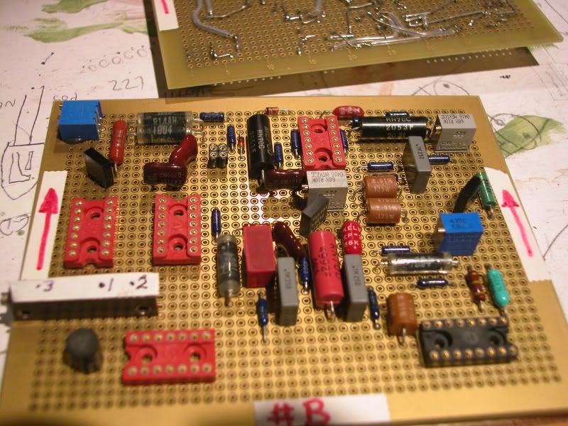
VCO (less the Dorritos):

(some good parts):
http://i5.photobucket.com/albums/y177/Midiot/DSCN1801.jpg
I tried three different fet's...MF102, 2n3819, 2n3823..all worked. That extra chip socket at the bottom is for a 49.9k DIP resistor (cv inputs).
-----------
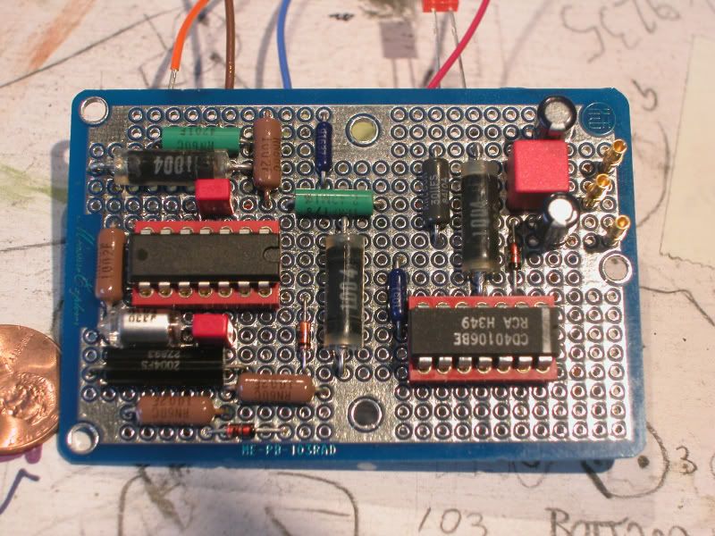
Signal to gate:

(back):
http://i5.photobucket.com/albums/y177/Midiot/dscn1806.jpg
-----------
Stereo Mixer:
http://i5.photobucket.com/albums/y177/Midiot/DSCN1802.jpg
-----------
Dual MS20 clone:
http://i5.photobucket.com/albums/y177/Midiot/cce7d545.jpg
-------------------
My workspace:
http://i5.photobucket.com/albums/y177/Midiot/DSCN1795.jpg
http://i5.photobucket.com/albums/y177/Midiot/DSCN1796.jpg
--------------------------
This is my first CV controlled synth, so let the newb questions beginnnn.... !! .......
VCO - waves look good on scope, but Pulsewidth control pot will not give me perfectly spaced square waves (longer bottoms w/shorter tops)....it approaches good spacing, but stops short. Does this matter?
When "tuning" for 1volt/1 octave, do I need to look up the standard frequencies and tune to them?....or should the frequencies just double per volt increase? (boy, that a basic Q, whew !) I have a circuit that puts out 1v - 5v, for tuning.
In other words, what should my frequency meter read as I increase by 1v steps?
Signal to Gate: - Works well. I'm using a CD40106 (same as 74C14 I believe). Puts out a 12v gate, is this too much? I assume it puts out whatever voltage it runs off of.
If you haven't noticed, they're all point-to-point wired... 
=FB= |
|
|
Back to top
|
|
 |
bigtex

Joined: Mar 30, 2006
Posts: 323
Location: Cupertino, California
|
 Posted: Tue Sep 12, 2006 7:52 pm Post subject: Posted: Tue Sep 12, 2006 7:52 pm Post subject:
|
  |
|
Wow! Cool stuff!
Hey, where did you get those vertical PCB mount potentiometers? I've been looking for something just like that. I want to use the potentiometers to mount a board parallel to a front panel.
Edit: it looks like you're using old components pulled from other boards. Is that true? That would sure make for some cheap devices! |
|
|
Back to top
|
|
 |
Scott Stites
Janitor


Joined: Dec 23, 2005
Posts: 4127
Location: Mount Hope, KS USA
Audio files: 96
|
 Posted: Tue Sep 12, 2006 8:22 pm Post subject: Posted: Tue Sep 12, 2006 8:22 pm Post subject:
|
  |
|
Definitely nice work there!
Yeah, the VCO tuning - just tune for doubling of frequency per volt.
The 12V gate IIRC is what to expect from Ray's signal to gate converter. In fact, the modules of his that I use, like the EG's, won't gate or trigger from 5V sources. I put in comparators on the inputs so they'd trigger on lower levels.
The pulse wave - not sure - by smaller at top, do you mean they tops are are starting to come together like a triangle wave?
Again, nice work indeed! Looks like bus wire with cut-to-length teflon sleeving, which I like to use.
Cheers,
Scott |
|
|
Back to top
|
|
 |
Freq Band

Joined: Sep 05, 2006
Posts: 57
Location: Los Angeles
|
 Posted: Wed Sep 13, 2006 12:36 pm Post subject: Posted: Wed Sep 13, 2006 12:36 pm Post subject:
|
  |
|
All of those parts are NOS (new old stock), except for a few chips and electrolytics. I have a surplus electronic store near by......some stuff is dated from the 1960's 
| Quote: | Hey, where did you get those vertical PCB mount potentiometers? I've been looking for something just like that. I want to use the potentiometers to mount a board parallel to a front panel.
|
Clarostat...can't remember the model#.....again, those were about 10 years old, but unused, still packaged. If you look at the blue pots below those, I epoxy'd them to the board. Just make sure you clean the surfaces first...maybe lightly sand them, and that'll probably be stronger than the others.
-------------
| Quote: | | The pulse wave - not sure - by smaller at top, do you mean they tops are are starting to come together like a triangle wave? |
No, The pulse width pot changes the space of every other vertical line in the squarewave (they remain upright).....the pot won't let me adjust them so they're equally spaced. I don't know if this a problem or not...yet. I may have to wait 'till every thing is hooked up together.
=============
I like using those boards with a ground plane on one side,,,,,but I gotta be carefull.....one tiny flake of metal will create a short !! So, I test the plane every 3rd or 4th time I add some components, so I know where to look for a problem. The worst place to get a flake lodged is under a 'lytic, or an IC socket (an air blast usually works). I don't connect anything to the plane till I know everything is working first. In fact, I'll probably coat it (a conformal coating) just before mounting it into the case. I've been reading that some components should not have a ground plane beneath them, as they could inject "stray capacitance" to the plane.........  ....I'm still a beginner. ....I'm still a beginner.
=FB= |
|
|
Back to top
|
|
 |
|


