mysterioz
Joined: Sep 15, 2006
Posts: 7
Location: Cincinnati
|
 Posted: Sat Sep 16, 2006 12:48 am Post subject:
Yamaha dd50 Posted: Sat Sep 16, 2006 12:48 am Post subject:
Yamaha dd50 |
  |
|
These are just the results of my first experiment. I haven't made any mods, and have only tested by grounding chip points. I played one of the presets while touching pins to ground. I haven't tested if any of these work with midi, nor have I tried connecting one ram to the other.
The only good points I found are on the LC33832P-80, and the Yamaha XR88920. I couldn't find any info on the the XR chips, but I think the LC38832P is a static ram chip or nvram.
Touching pins on the left of the LC chip to ground made interesting filter sounding effects, but grounding the pins on the right made overload distortion. The top pins of the XR chip made sounds like the PCM samples where modulating the melody being played. My guess was another pcm ram chip, but I have no idea. The bottom pins did similar things, but a couple made an overload distortion like the right LC contacts.
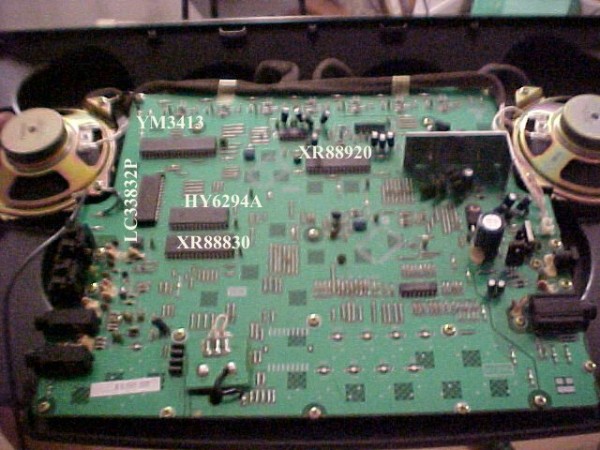
| Description: |
| Here are the chips laid out |
|
| Filesize: |
74.38 KB |
| Viewed: |
554 Time(s) |
| This image has been reduced to fit the page. Click on it to enlarge. |
|
| Description: |
| Pins of the left where the best when grounded. Pins on the right made overload distortion. Will try grounding with capacitor or resisistors. |
|
| Filesize: |
63.83 KB |
| Viewed: |
444 Time(s) |
| This image has been reduced to fit the page. Click on it to enlarge. |

|
| Description: |
| Some where better than others, but everything did something. |
|
| Filesize: |
72.34 KB |
| Viewed: |
467 Time(s) |
| This image has been reduced to fit the page. Click on it to enlarge. |

|
|
|
mysterioz
Joined: Sep 15, 2006
Posts: 7
Location: Cincinnati
|
| Posted: Sat Sep 16, 2006 2:40 pm Post subject:
chips and specs |
|
|
YM3413 - DSP -i I haven't been able to find much info except that Yamaha uses it for high end stereos in Japan. Since all the sites where in Japanese, I could only guess at what google translator was trying to tell me, but it seems they use it for adding reverb and other sound effects. My guess is it is the brain of the unit, programmed to be the CPU. Which is why I stayed away from it. Although some of the chips are different, the inside of this guys stereo looks amazingly similar http://translate.google.com/translate?hl=en&sl=ja&u=http://www.kameson.com/audio/DSP-100.htm&sa=X&oi=translate&resnum=22&ct=result&prev=/search%3Fq%3Dym3413%26num%3D100%26hl%3Den%26hs%3DiOz%26lr%3D%26safe%3Doff%26client%3Dfirefox-a%26rls%3Dorg.mozilla:en-US:official%26sa%3DG
HY6264A - 8x8 cmos ram http://www.ortodoxism.ro/datasheets/hynix/HY6264A-15.pdf
Looking over the datasheet it looks like I was trying the address pins rather than the i/o pins. A capacitor on the i/o pins might screw with the data on that pin. All the pins I tried grounding caused the machine to stop, sometimes recoverable but mostly just crash. Not sure what is stored on here, maybe your 1 recordable rhythm? Nothing useful found yet
XR88920 - ??? - no data, I found an MC88920 which is a PLL clock driver. I don't know what this does, but grounding pins produced effects on every pin I tried. A couple overloaded, but recovered. Probably want to put variable resistors with body contacts to short pins???
LC33832P-80 - 256x8 pseudo static RAM (http://www.ortodoxism.ro/datasheets/sanyo/LC33832SL.pdf) Looks like pins 1-10 are the ones that where working for me, and pins 21, 23-26 are also address pins. The data i/o pins and other pins where causing intense feedback, but the machine usually recovered. My guess is I need a resistor to lower the current, although better bends would probably be to mess with the data lines.
XR88830 has no data, and I did not mess with it yet. I was guessing it was for midi (uart?) but perhaps both XR chips are some kind of EPROM, one with sounds, one with the software. The DSP then works as a CPU and mixer, and outputs the sound via internal D/A converter???
That is my guess so far. The insides look a lot different than the DD-6, but the pics on bent wiki don't identify chips, so it's hard to tell if there are any comparable mods. One mod I can think of is trying to replace the Ram with NV ram so it will save settings and your one saved patter after power down. Perhaps the smaller ram chip is for your rhythm, and the larger loads the sounds from somewhere?
I'd like to hear from anyone else who has tried modding any DD-. Listening online, the modded dd-50's had the best sounds I thought. I'm planning on ripping this apart into a rack mount unit with 1/4 jack inputs for each drum trigger, so I will be able to attach a piezo to a hand drum and use as a trigger. I'd like to add a switch on each to allow it to accept CV gate triggers. Since the unit is designed for 2 (or is it 3?) velocity sensitivities, if I can find the voltage points, I can set each drum trigger to accept 2 CV inputs, doubling the amount of midi samples I can trigger from my sampler, using the dd-50 as a simple CV gate to midi sampler trigger.
There are 2 crystals, one marked 9.40t and 16.00x, both have 3 leads. From looking over other Yamaha synth chips, it is likely one crystal clocks the computer and the other is used by the computer for generating sound. I think this is a PCM, so maybe one is used to created the soundwave inside the DSP. I don't know much about PCM, but I think if the xr888920 was some kind of PLL, it could be used to create the final soundwave. What is a good way to mess with the clock?
After I take a trip to Radio Shack, I will take off the shield on the other side of the board and start doing some trace routing. I'll post some more pics too.
I hope this gives others a place to start or maybe some inspiration. If anyone has any ideas for me to try or experience, please post.
Happy Bending! |
|

 Forum index » DIY Hardware and Software » Circuit Bending
