| Author |
Message |
Funky40
Joined: Sep 24, 2005
Posts: 875
Location: Swiss
Audio files: 1
G2 patch files: 5
|
 Posted: Wed Sep 05, 2007 8:32 am Post subject: Posted: Wed Sep 05, 2007 8:32 am Post subject:
|
  |
|
WOW,
one Panel is nicer than the other !!!
Sliders:
Since i saw this Video of that Sequenzer with sliders,
i like to have such a thing too.
http://www.youtube.com/watch?v=xu8doblzfXU the Homepage http://www.studiomanus.com/index.htm
Has anybody a tip for good sliders ?
60mm ? ( more on the cheaper side if possible )
100mm which are sliding as smooth as those in the Video ?
thanks for all the Layouts |
|
|
Back to top
|
|
 |
State Machine
Janitor


Joined: Apr 17, 2006
Posts: 2810
Location: New York
Audio files: 24
|
| Posted: Wed Sep 05, 2007 9:21 am Post subject:
|
|
|
| Quote: | | because you basically wire everything to the panel when it's laying out on your table, and then you just...plug it in! |
Yes, Scott, always a plus!
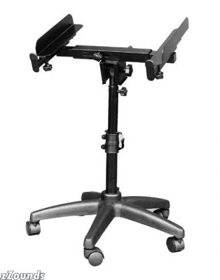
I have a couple of tips for building, to avoid neck fatigue and chiropractor bills, is to use a portable mixer stand, if you have one handy, one with adjustable width, tilt and height, and place the panel on that. As you are wiring, you can put it at any comfortable height or angle to get your soldering done comfortably.
For circuit boards, I use Panavise units. They are a bit of cash but well worth the money if you do lots of building. Here is a picture of a unit similar to mine. Again, this could save lots of money by not having to pop so many pain killers. Unless you like that sort of thing.
| Description: |
|
| Filesize: |
7.2 KB |
| Viewed: |
9398 Time(s) |

|
| Description: |
|
| Filesize: |
12.38 KB |
| Viewed: |
9398 Time(s) |
|
|
|
|
Back to top
|
|
|
bugbrand

Joined: Nov 27, 2005
Posts: 846
Location: Bristol, UK
Audio files: 1
G2 patch files: 1
|
| Posted: Thu Sep 06, 2007 2:47 am Post subject:
|
|
|
Coming along nicely....!....
| Description: |
| Front'o'klee with everything mounted except the extra clock circuit |
|
| Filesize: |
146.7 KB |
| Viewed: |
369 Time(s) |
| This image has been reduced to fit the page. Click on it to enlarge. |

|
| Description: |
| Back-side---- First stages of the massive wiring job! |
|
| Filesize: |
182.84 KB |
| Viewed: |
382 Time(s) |
| This image has been reduced to fit the page. Click on it to enlarge. |

|
_________________
http://www.bugbrand.co.uk
http://www.bugbrand.blogspot.com |
|
|
Back to top
|
|
|
mono-poly

Joined: Jul 07, 2004
Posts: 937
Location: Rotterdam, Netherlands
Audio files: 2
|
| Posted: Thu Sep 06, 2007 3:10 am Post subject:
|
|
|
| Looking good man! |
|
|
Back to top
|
|
|
numbernone
Joined: Aug 16, 2006
Posts: 477
Location: new york city
|
| Posted: Thu Sep 06, 2007 8:08 am Post subject:
|
|
|
WHOA!!! I have been out of the loop for a few weeks...did the Klee boards go on sale already?
Really beautiful work everybody is doing. I am liking the slider option more and more all the time. Could somebody point towards the make of some of their slider pots? I have never used them but really love the visual aspect. |
|
|
Back to top
|
|
|
State Machine
Janitor
Joined: Apr 17, 2006
Posts: 2810
Location: New York
Audio files: 24
|
| Posted: Thu Sep 06, 2007 8:56 am Post subject:
|
|
|
| Quote: | | Coming along nicely....!.... |
Sure is man !! Love it. Nice work Tom 
Bill |
|
|
Back to top
|
|
|
State Machine
Janitor
Joined: Apr 17, 2006
Posts: 2810
Location: New York
Audio files: 24
|
| Posted: Thu Sep 06, 2007 9:02 am Post subject:
|
|
|
| Quote: | | WHOA!!! I have been out of the loop for a few weeks...did the Klee boards go on sale already? |
Thanks ! Well, the first four "production" prototypes are being built by TEAM KLEE:
Scott Stites
Andrew Sharp (Uncle Krunkus)
Tom "Bug Brand" Bugs
William Manganaro (State machine)
This prototype phase will continue until we all built and suficiently test them. Once Scott decides it good to go, then ... I will take orders for part kits for a period of one month and Scott will ... (This is where Scott gives his answer) .....
This is as much as I can answer
Bill |
|
|
Back to top
|
|
|
Scott Stites
Janitor

Joined: Dec 23, 2005
Posts: 4127
Location: Mount Hope, KS USA
Audio files: 96
|
| Posted: Thu Sep 06, 2007 9:38 am Post subject:
|
|
|
Scott will order the boards, ship them to mosc, and when the store is ready to handle it, PM all those who've reserved boards letting them know they're available for purchase! There are 74 individuals who've got 103 board sets reserved. The board sets will be purchased through the EM store.
Forgot to mention, I dig the Fonik Green. In fact, I think sliders not only look better and take less horizontal room, but I can see them as being preferable as far as telling what's going on at a glance. Not having the technology to cut straight lines in aluminium (I'm barely able to drill round holes) I went with rotary pots. I did have one nice guy offer to cut me a panel, and I may take him up on that on the next Klee I build.
Cheers,
Scott
_________________
My Site |
|
|
Back to top
|
|
|
Scott Stites
Janitor
Joined: Dec 23, 2005
Posts: 4127
Location: Mount Hope, KS USA
Audio files: 96
|
| Posted: Thu Sep 06, 2007 9:49 am Post subject:
|
|
|
Man, the Bugbrand version is going like gangbusters! Rumour has it he's fitting an extra surprise clock-board into it. I'm glad to see what a banana version will look like, too.
_________________
My Site |
|
|
Back to top
|
|
|
norman phay

Joined: Jun 29, 2007
Posts: 176
Location: North-East England
Audio files: 1
|
| Posted: Thu Sep 06, 2007 10:37 am Post subject:
|
|
|
| That looks goddamn awesome, bugbrand. |
|
|
Back to top
|
|
|
norman phay
Joined: Jun 29, 2007
Posts: 176
Location: North-East England
Audio files: 1
|
| Posted: Thu Sep 06, 2007 10:39 am Post subject:
|
|
|
| As an aside, did either of the guys who were working on the frac-format circular sequencer style layout get any further? Anyone have a .fpd file I can have a play around with? |
|
|
Back to top
|
|
|
a.b.o.z.

Joined: Feb 07, 2007
Posts: 351
Location: Zagreb, Croatia
Audio files: 7
G2 patch files: 4
|
| Posted: Thu Sep 06, 2007 10:44 am Post subject:
|
|
|
didn't go any further. that last version is the final one. got aluminum sheet today. next week is cnc time. I'll keep you posted.
cheers
Ivan
edit:mine isn't frack-rack |
|
|
Back to top
|
|
|
abis

Joined: Apr 28, 2007
Posts: 35
Location: Toronto, Ontario
Audio files: 1
|
| Posted: Thu Sep 06, 2007 11:20 am Post subject:
wiring tutorials? |
|
|
These electro-music Klee's are looking just awesome! And the build pictures are giving me a great sense of what goes in to putting one together. Thanks to all for that.
Does anyone know of any good tutorials to help out a noob like me make sense of things like strap wiring and harnessing?
Cheers,
Andrew |
|
|
Back to top
|
|
|
Scott Stites
Janitor
Joined: Dec 23, 2005
Posts: 4127
Location: Mount Hope, KS USA
Audio files: 96
|
| Posted: Thu Sep 06, 2007 12:31 pm Post subject:
|
|
|
Hey Andrew,
Strap wiring is applying the wiring for all of the common connections the panel components have. For example, the pots each have to have a ground connection. If you consider that there are sixteen pots for the programming pots alone, that's sixteen ground connections right there. Instead of running a ground wire for each pot to the boards, you connect the ground points of each wire together and then run one wire to that common connector from the board.
Here's a page from the electro-music Klee Front Panel/Interconnect Schematic. If you take a look at it, you'll probably spot the "landmarks" on Bill and Tom's strap wiring pictures.
Note how the top and bottom of the gate bus switches all have a common connection (these are actually busses 1 and 3). The center of the switches each have their own individual connection - that makes up Gate Bus 2. Those connections each require an individual wire going back to the board. If you look at Bill and Tom's pics, you'll spot that row of switches with a length of bus wire connecting the top and bottom of the switches, but they haven't connected anything to the middle pin because they have yet to begin wiring the wires that connect to the board.
Also note that the merge switches, clock LED and the Manual Step Switch all have a common connection - they all connect to Digital Ground. So, that's another common connection you can wire into the panel. Wiring all of these common connections before wiring in the harness wires makes things a lot easier to assemble. Don't worry - the build doc will take you through the various steps.
The harnesses are not all as bad as it sounds. If you decide to use connectors, you can build the harnesses up ahead of time. This involves taking the wires, crimping or soldering pins onto them, and shoving those pins into a connector housing. The housing may hold two, three four, six wires or eight wires, and that's how many wires you shove into them. You end up with a housing with a number of wires hanging off the end. When it's time to put the Klee together, the loose ends of the wires solder to the panel parts, and the housing connects to the appropriate connector on the board.
Cheers,
Scott
| Description: |
|
| Filesize: |
46.63 KB |
| Viewed: |
229 Time(s) |
| This image has been reduced to fit the page. Click on it to enlarge. |

|
_________________
My Site |
|
|
Back to top
|
|
|
fonik

Joined: Jun 07, 2006
Posts: 3950
Location: Germany
Audio files: 23
|
| Posted: Thu Sep 06, 2007 1:42 pm Post subject:
|
|
|
| Scott Stites wrote: | | I dig the Fonik Green. In fact, I think sliders not only look better and take less horizontal room, but I can see them as being preferable as far as telling what's going on at a glance. |
BTW i reviewed my layout, did some little changes and ordered it today:

does anybody have any experiences with coloring screws?
_________________

cheers,
matthias
____________
Big Boss at fonitronik
Tech Buddy at Random*Source |
|
|
Back to top
|
|
|
goodrevdoc

Joined: Sep 11, 2006
Posts: 288
Location: Philadelphia, PA
Audio files: 1
|
| Posted: Thu Sep 06, 2007 3:48 pm Post subject:
|
|
|
Freaking AMAZING work guys. I must admit though, I am sort of partial to Bugs' panel. Although mine will most likely end up looking like Scott's. Not that that's a bad thing. I happen to like the cold war era military test equipment look myself. That's what got me started in electronics in the first place. Plus, I am sadly also barely able to drill round holes. 
-justin |
|
|
Back to top
|
|
|
creekree

Joined: Mar 30, 2006
Posts: 192
Location: Morgenland Neukölln
Audio files: 1
|
| Posted: Thu Sep 06, 2007 5:28 pm Post subject:
|
|
|
whew fonik, i like your panel!
what is the travel of your sliders?
i guess you want to color the screws for your sliders, eh? dont know how to do that, but another idea would have been to mount the sliders on two strips of metal and then to mount this "slider chassis" to the front panel. this way you´d end up with maybe 8 holes for the sliders on the panel instead of 32.
of course the shafts of the sliders have to be long enough to allow that.
hm, if your frontpanel is going to be painted (not anodized) you can get away with painting the screws heads in the same color. i did that with my x0xb0x.
ok, in german: (sorry guys!!):
(dies ist jetzt nicht exklusiv für den klee seq, aber adaptierbar für viele anwendungen. funktioniert ganz gut, wenn man die geduld hat)
die bohrlöcher versenken (oder von schaeffer versenken lassen), passende senkkopfschrauben (lieber zu lang als zu kurz!) einsetzen, von der rückseite mit sprengring und kontermutter versehen. festziehen, evtl loctite auf die schraube, diese verbindung soll sich nicht mehr lösen. nie mehr.
nun den schraubenkopf zuspachteln, schleifen, panel lackieren (legende mit lazertran machen - super zeug!), klarlackieren.
jetzt hat man ein frontpanel mit gewindebolzen auf der rückseite aber keinen erkennbaren schraubköpfen auf der vorderseite.
als nächstes abstandshalter aus messingröhrchen oder ähnlichem (kugelschreiber, gardinenstange, was-auch-immer) herstellen, pcb aufstecken, mutter drauf, fertig.
 |
|
|
Back to top
|
|
|
Uncle Krunkus
Moderator

Joined: Jul 11, 2005
Posts: 4761
Location: Sydney, Australia
Audio files: 52
G2 patch files: 1
|
| Posted: Thu Sep 06, 2007 5:52 pm Post subject:
|
|
|
| fonik wrote: | | does anybody have any experiences with coloring screws? |
From my experience;
Wash them in soapy water.
Dry well.
Rinse in some methylated spirit.
Drain on some paper towel. (don't touch the heads from here on)
When the methylated spirit has evaporated off.
Pick each one up by the thread and colour with a permanent marker, or the "pens" of hobby paint you can get for plastic models are more durable.
They won't deal with being rubbed very much, but from my experience, once they're in place, you won't touch them very much anyway.
_________________
What makes a space ours, is what we put there, and what we do there. |
|
|
Back to top
|
|
|
blue hell
Site Admin

Joined: Apr 03, 2004
Posts: 24571
Location: The Netherlands, Enschede
Audio files: 307
G2 patch files: 320
|
| Posted: Thu Sep 06, 2007 5:53 pm Post subject:
|
|
|
| creekree wrote: | | ... mutter drauf, fertig |
| babelfish wrote: | | the boreholes sink (or of more schaeffer to sink leave), suitable countersunk screws (rather too long than too short!) , provided by the back with circlip and lock nut tighten, evtl if Loctites use this connection to screw, are not any longer to separate never more now the screw head zuspachteln, sharpen, panel paint (putting with lazertran to make - super things!), clear-paints now has one a front panel with screw mountings on the back however no recognizable to screw-cut back on the front next spacer of brass tubes or the like (ball-point pen, curtain rod, what also always) to make, pcb attach, nut/mother drauf, finished. |
That is .. use sink head screws and fasten those with a nut, a toothed washer, and locktite so they'll not loosen again. Flatten screw head, paint the panel over the screws, use lazertran. You'll end up with a front panel having wire ends on the back side and no visible screws on the front side. Use the wire ends to attach your PCB to the front panel, using suitable stand offs.
Does that make sense?
_________________
Jan
also .. could someone please turn down the thermostat a bit.
 |
|
|
Back to top
|
|
|
Uncle Krunkus
Moderator
Joined: Jul 11, 2005
Posts: 4761
Location: Sydney, Australia
Audio files: 52
G2 patch files: 1
|
| Posted: Thu Sep 06, 2007 5:58 pm Post subject:
|
|
|
| creekree wrote: | | i guess you want to color the screws for your sliders, eh? dont know how to do that, but another idea would have been to mount the sliders on two strips of metal and then to mount this "slider chassis" to the front panel. this way you´d end up with maybe 8 holes for the sliders on the panel instead of 32. |
My "slider plate" is going beyond the pattern and gate bus switches (which have quite long shafts) So there won't be any mounting screws for the sliders showing at all.
_________________
What makes a space ours, is what we put there, and what we do there. |
|
|
Back to top
|
|
|
creekree
Joined: Mar 30, 2006
Posts: 192
Location: Morgenland Neukölln
Audio files: 1
|
| Posted: Thu Sep 06, 2007 5:59 pm Post subject:
|
|
|
hehe babelfish sure is funny...
in short: i was describing how to make screw heads completely disappear.
your description, jan, is almost accurate - although its not "wire ends" (dont know what you mean by that), you'll have threaded bolts sticking out on the back of your panel to which you can fix your pcb (fader... whatever) to. |
|
|
Back to top
|
|
|
blue hell
Site Admin
Joined: Apr 03, 2004
Posts: 24571
Location: The Netherlands, Enschede
Audio files: 307
G2 patch files: 320
|
| Posted: Thu Sep 06, 2007 6:10 pm Post subject:
|
|
|
| creekree wrote: | | although its not "wire ends" |
Erm, that was pretty literal from dutch "draadeind" ... where is the hell is the dictionary ... its a big red book .. can't miss it ... hmm it's not in it ...
right, stud might be the word, although things get a bit confusing when I look for pictures in google 
_________________
Jan
also .. could someone please turn down the thermostat a bit.
|
|
|
Back to top
|
|
|
Scott Stites
Janitor
Joined: Dec 23, 2005
Posts: 4127
Location: Mount Hope, KS USA
Audio files: 96
|
| Posted: Thu Sep 06, 2007 7:22 pm Post subject:
|
|
|
| Quote: | | I happen to like the cold war era military test equipment look myself. |
Word. And our powerful (semi)circular pot-holes will naturally deflect the effects of the inevitable EMP, while those slotted numbers will allow the lines of flux right on through. The cockroaches will be playing our military surplus Klee's long after we're gone. 
_________________
My Site |
|
|
Back to top
|
|
|
The Alison Project

Joined: Jul 21, 2006
Posts: 187
Location: Canada
Audio files: 2
|
| Posted: Thu Sep 06, 2007 9:27 pm Post subject:
|
|
|
| drool...... soon I will Klee |
|
|
Back to top
|
|
|
Uncle Krunkus
Moderator
Joined: Jul 11, 2005
Posts: 4761
Location: Sydney, Australia
Audio files: 52
G2 patch files: 1
|
| Posted: Fri Sep 07, 2007 12:32 am Post subject:
|
|
|
BTW
That latest layout is the dog's bollocks Fonik!
I love the large sweeping semicircular lines which kind of divide and tie the design together at the same time.
_________________
What makes a space ours, is what we put there, and what we do there. |
|
|
Back to top
|
|
|
|

 Forum index » DIY Hardware and Software » Klee sequencer
