| Author |
Message |
LetterBeacon
Joined: Mar 18, 2008
Posts: 454
Location: London, UK
|
 Posted: Thu May 08, 2008 2:29 am Post subject: Posted: Thu May 08, 2008 2:29 am Post subject:
|
  |
|
| In this post http://electro-music.com/forum/post-62184.html dnny recommends using Maplin's 2N3819 instead of the MPF102 (which doesn't seem to be available in the UK). So that may not be the problem. |
|
|
Back to top
|
|
 |
asafnetzer
Joined: Jun 16, 2007
Posts: 112
Location: Israel
|
| Posted: Thu May 08, 2008 3:01 am Post subject:
|
|
|
Hi, It's really hard to see whats going on the board 
If you can post pictures of the lower side it could help more.
In the meanwhile try to check the connections again, look for solder bridges or cold solder points.
Best regards,
Asaf |
|
|
Back to top
|
|
|
LetterBeacon
Joined: Mar 18, 2008
Posts: 454
Location: London, UK
|
| Posted: Thu May 08, 2008 3:22 am Post subject:
|
|
|
| Well I just compared the coloured resistor bands on my resistors to the ones on the Ruby website and they are different! This must mean my resistor values are wrong, surely? |
|
|
Back to top
|
|
|
LetterBeacon
Joined: Mar 18, 2008
Posts: 454
Location: London, UK
|
| Posted: Thu May 08, 2008 3:38 am Post subject:
|
|
|
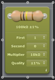
Resistor bands are universal, aren't they? I've just checked the colours on my resistors with this Graphical Resistor Calculator and mine have very different values!
If I go into Maplin and specify colour bands, I should come out with the correct resisitors, right? |
|
|
Back to top
|
|
|
Uncle Krunkus
Moderator

Joined: Jul 11, 2005
Posts: 4761
Location: Sydney, Australia
Audio files: 52
G2 patch files: 1
|
| Posted: Thu May 08, 2008 3:50 am Post subject:
|
|
|
If you've got a multimeter of some kind, check the resistor values which you're unsure of.
Some resistors have a 3 band code, some have a 4 or sometimes 5 band code.
For example, a 27K resistor could be
Red, Purple, Orange (2,7 and 3(0s)) or
Red, Purple, Black, Red (2,7,0 and 2(0s))
Get in the habit of checking what you're putting in somehow. On a larger project, realising that you've soldered in 30*10K when they should have been 100K is a real pain in the arse. Getting two values swapped could lead to a fault that you never find. Checking them might seem tedious, but having things work first try will put a smile on your dial every time.
_________________
What makes a space ours, is what we put there, and what we do there. |
|
|
Back to top
|
|
|
LetterBeacon
Joined: Mar 18, 2008
Posts: 454
Location: London, UK
|
| Posted: Thu May 08, 2008 4:01 am Post subject:
|
|
|
Ok, so I think I have 4 band resistors with a 5th for tolerance. They are:
My 1.5M is brown, green, black, yellow + brown = 150 000 = 1.5M which is correct
My 3.9K is orange, white, black, brown +brown = 3900 = 3.9K which is correct
My 10R is brown, black, black, gold +brown = 10.0 which is correct.
So it looks like my resistors are ok after all. I was comparing mine with the 3 band ones in the Ruby example. |
|
|
Back to top
|
|
|
asafnetzer
Joined: Jun 16, 2007
Posts: 112
Location: Israel
|
|
|
Back to top
|
|
|
LetterBeacon
Joined: Mar 18, 2008
Posts: 454
Location: London, UK
|
| Posted: Thu May 08, 2008 5:55 am Post subject:
|
|
|
Cool, thanks for that - just installed it!
I've had a look on the underside and I can't see any cold solder joints or bridges. I may have to get a magnifying glass to have a proper look though. |
|
|
Back to top
|
|
|
Wild Zebra

Joined: Apr 28, 2005
Posts: 806
Location: Ohio
Audio files: 5
|
| Posted: Thu May 08, 2008 8:51 am Post subject:
|
|
|
Make sure you cut the trace on the board as well. Thats the red square with the red dot in the middle on the layout by the cap in the top left. You'll have to use a drill bit or something to break the copper so there is not a connection. Got me??
_________________
"your stripes are killer bro" |
|
|
Back to top
|
|
|
LetterBeacon
Joined: Mar 18, 2008
Posts: 454
Location: London, UK
|
| Posted: Thu May 08, 2008 9:17 am Post subject:
|
|
|
| Yep, I've broken it there and in between the pins of the 386. A friend thought that the biasing might be wrong on the 386 and it's getting too much negative feedback, but if I've got the right resistors in then I don't think that should be a problem. |
|
|
Back to top
|
|
|
Uncle Krunkus
Moderator
Joined: Jul 11, 2005
Posts: 4761
Location: Sydney, Australia
Audio files: 52
G2 patch files: 1
|
| Posted: Thu May 08, 2008 4:09 pm Post subject:
|
|
|
| LetterBeacon wrote: | | My 1.5M is brown, green, black, yellow + brown = 150 000 = 1.5M which is correct |
You're missing a zero here, (i'm just being pedantic ) but yes, the code is correct.
_________________
What makes a space ours, is what we put there, and what we do there. |
|
|
Back to top
|
|
|
LetterBeacon
Joined: Mar 18, 2008
Posts: 454
Location: London, UK
|
| Posted: Mon May 19, 2008 9:26 am Post subject:
|
|
|
After work commitments meant I had to take a break from this project, I started on it again with renewed vigour today. I doubled checked for cold solder joints and shorts etc. to no avail. Problems that I have now fixed are:
I had my 220uf capacitor the wrong way round
I had the wires going to the 1 & 3 lugs on the volume and gain pots the wrong way round
I had the jumper wire that should go from 10J to 10B going from 10J to 10B
It's still now working, however! It still oscillates but at a slightly higher pitch, and turning the gain pot determines how far I can turn the volume pot before the oscillation kicks in! I'm at my wit's end!
I'll try and post a picture of the underside tonight, but I think it might be easier to start again! |
|
|
Back to top
|
|
|
LetterBeacon
Joined: Mar 18, 2008
Posts: 454
Location: London, UK
|
| Posted: Mon May 19, 2008 3:24 pm Post subject:
|
|
|
I've just replaced the 386 in case I had blown it with the bad connections - same thing unfortunately, is just makes a loud square wave sound.
I've taken a couple of pictures of the solder side of the stripboard in case anyone can see anything immediately obviously wrong (apologies for the terrible image quality):

 |
|
|
Back to top
|
|
|
LetterBeacon
Joined: Mar 18, 2008
Posts: 454
Location: London, UK
|
| Posted: Tue May 20, 2008 7:45 am Post subject:
|
|
|
| If you have a potentiometer with the lugs pointing upwards and you're looking at it from the back (i.e. with the spindle pointing away from you), are the lugs numbered 1 2 & 3 from left to right? |
|
|
Back to top
|
|
|
Uncle Krunkus
Moderator
Joined: Jul 11, 2005
Posts: 4761
Location: Sydney, Australia
Audio files: 52
G2 patch files: 1
|
| Posted: Tue May 20, 2008 7:58 am Post subject:
|
|
|
It doesn't really matter as long as the middle connection (2) goes to the right place. Swapping the outside two just reverses the effective rotation.
_________________
What makes a space ours, is what we put there, and what we do there. |
|
|
Back to top
|
|
|
LetterBeacon
Joined: Mar 18, 2008
Posts: 454
Location: London, UK
|
| Posted: Tue May 20, 2008 8:53 am Post subject:
|
|
|
| So, in this case, the volume pot will be the wrong way round? Turning it clockwise will make it louder? |
|
|
Back to top
|
|
|
LetterBeacon
Joined: Mar 18, 2008
Posts: 454
Location: London, UK
|
| Posted: Tue May 20, 2008 1:51 pm Post subject:
|
|
|
I went to modman's site where he has built himself a working Ruby amp. He has a list of correct pin voltages on there which are:
| modman wrote: |
2N5457 JFET:
Drain = 9.18V;
Source = 0.84V;
Gate = 0.00V
LM386 opamp:
1 = 1.34V;
2, 3 and 4 = 0.00V;
5 = 4.56V;
6 = 9.18V;
7 = 4.64V;
8 = 1.34V |
The voltage between the battery and the pins on my 2N3819 are as follows:
Drain = 9.30
Source = 9.30
Gate = 8.67
This must be part of the problem - does this indicate a broken FET? |
|
|
Back to top
|
|
|
Uncle Krunkus
Moderator
Joined: Jul 11, 2005
Posts: 4761
Location: Sydney, Australia
Audio files: 52
G2 patch files: 1
|
| Posted: Tue May 20, 2008 4:54 pm Post subject:
|
|
|
It's either a dead FET or connection errors, and I think you've ruled out errors in the build, so I'd replace the FET and see what happens. I'm still not 100% sure that the FET you're using is a good substitute, but wait till you've tried another one before you go down that path. 
_________________
What makes a space ours, is what we put there, and what we do there. |
|
|
Back to top
|
|
|
Uncle Krunkus
Moderator
Joined: Jul 11, 2005
Posts: 4761
Location: Sydney, Australia
Audio files: 52
G2 patch files: 1
|
| Posted: Tue May 20, 2008 4:59 pm Post subject:
|
|
|
When you take the FET out, check what voltage you have at the Gate connection. (Where the input comes in) With no input connected this should be at 0V.
I was just wondering as the figures you took could point to the FET being saturated somehow.
_________________
What makes a space ours, is what we put there, and what we do there. |
|
|
Back to top
|
|
|
LetterBeacon
Joined: Mar 18, 2008
Posts: 454
Location: London, UK
|
| Posted: Wed May 21, 2008 12:00 am Post subject:
|
|
|
| Uncle Krunkus wrote: | When you take the FET out, check what voltage you have at the Gate connection. (Where the input comes in) With no input connected this should be at 0V.
I was just wondering as the figures you took could point to the FET being saturated somehow. |
Ok cool thanks. When you say "take the FET out, check what voltage you have at the Gate connection" I don't quite understand where to place the points of the multimeter. Surely if the FET isn't in the circuit anymore it would read 0v? |
|
|
Back to top
|
|
|
Uncle Krunkus
Moderator
Joined: Jul 11, 2005
Posts: 4761
Location: Sydney, Australia
Audio files: 52
G2 patch files: 1
|
| Posted: Wed May 21, 2008 1:06 am Post subject:
|
|
|
I mean check the voltage at the point where the gate would connect. The junction of the 1M5 resistor and the input.
_________________
What makes a space ours, is what we put there, and what we do there. |
|
|
Back to top
|
|
|
LetterBeacon
Joined: Mar 18, 2008
Posts: 454
Location: London, UK
|
| Posted: Wed May 21, 2008 5:32 am Post subject:
|
|
|
Is the FET the wrong way round on the stripboard layout?

According to asafnetzer's picture here:

The FET pinout is 1 = drain, 2 = source & 3 = gate
According to the Ruby diagram here:

The input goes to the gate, but in the stripboard layout the input is going pin 1, the drain. The FET needs to be turned round, I think. Can someone confirm? |
|
|
Back to top
|
|
|
Uncle Krunkus
Moderator
Joined: Jul 11, 2005
Posts: 4761
Location: Sydney, Australia
Audio files: 52
G2 patch files: 1
|
| Posted: Wed May 21, 2008 11:45 am Post subject:
|
|
|
If you were using an MPF102 then the gate would be pin3 (according to that pic) and yes the layout looks the wrong way around. If you're using the 2N3819, the gate is pin 2 and you need to get that pin to the input. (The source and drain are often interchangeable, but for this design I'd try and get them right. Source to +ve)
What FET are you using? I thought you weren't using the MPF102.
_________________
What makes a space ours, is what we put there, and what we do there. |
|
|
Back to top
|
|
|
LetterBeacon
Joined: Mar 18, 2008
Posts: 454
Location: London, UK
|
| Posted: Wed May 21, 2008 12:01 pm Post subject:
|
|
|
Yes, I am using the 2N3819, but I soldered it onto the circuit board using the stripboard as a guide not the circuit diagram (i.e. I have the gate pin on the 2N3819 into 5a, not 5c as it should be). I'm back from work now so I'll be able to test that I'm getting 0v at the gate connection and I'll also be able to put a new 2N3819 onto the board correctly.
Thanks for your help! |
|
|
Back to top
|
|
|
LetterBeacon
Joined: Mar 18, 2008
Posts: 454
Location: London, UK
|
| Posted: Wed May 21, 2008 1:14 pm Post subject:
|
|
|
I've put a new FET in with the correct pins in the correct holes and I now get a buzzing from the speaker as you'd normally expect from a guitar amp - progress! Unfortunately when I plug my guitar in I don't get a sound although the buzzing gets louder when I tap the guitar strings, so I guess this must mean I've got some connections right!
| Quote: | | When you take the FET out, check what voltage you have at the Gate connection. (Where the input comes in) With no input connected this should be at 0V. |
To do this, should I put one point of the meter on the 9v rail and one on the Gate connection? When I did that I got a reading of around 3v - does this indicate that I have a short somewhere?
I have taken new readings from the pins of the new FET they are:
Drain = 9.29
Source = 9.29
Gate = 8.67
Really please that it's stopped oscillating and is sounding a bit more like an amp! |
|
|
Back to top
|
|
|
|

 Forum index » DIY Hardware and Software