| Author |
Message |
Wout Blommers

Joined: Sep 07, 2003
Posts: 4529
Location: The Hague - The Netherlands
Audio files: 123
G2 patch files: 12
|
 Posted: Thu Oct 23, 2008 7:13 am Post subject: Posted: Thu Oct 23, 2008 7:13 am Post subject:
 110-115V to 220-230V or visa versa 110-115V to 220-230V or visa versa
Subject description: An illustrated Manual |
  |
|
Disclaimer: The author doesn't take any responsibilities for damaging the synth or hurting yourself in any way. It is an electric device!
1 Disconnect the synth from the power.
2 Remove all connectors from the back:
Headphone,
Out cables,
Sustain pedal,
Control pedal,
MidiIn and MidiOut,
PCMCIA card, and, if possible,
Power cable (please don't cut it away!).
3 Remove everything on top of the synthesizer.
4 Using a Phillips screwdriver remove:
* the two large screws at the bottom of the synth, right underneath the ModWheel and halfway the synth (the rest keeps the boards and keyboard attached to the bottom,
* the four (sometimes three or five) screws on the back of the (red) hood,
* the two screws at the front of the sides and only loosen the two with the washer (see picture) and leave these in place: they keep the hood fixed to the bottom of the synth, so you don't have to disconnect any inside cables!
5 Open the hood...
(Using two hands at the front corners of the red hood while slowly lifting it)
| Description: |
| Screw at the back of the side panel. |
|
| Filesize: |
46.89 KB |
| Viewed: |
108848 Time(s) |

|
Last edited by Wout Blommers on Sat Oct 25, 2008 2:17 am; edited 18 times in total |
|
|
Back to top
|
|
 |
Wout Blommers

Joined: Sep 07, 2003
Posts: 4529
Location: The Hague - The Netherlands
Audio files: 123
G2 patch files: 12
|
 Posted: Thu Oct 23, 2008 7:17 am Post subject:
110-115V to 220-230V or visa versa Posted: Thu Oct 23, 2008 7:17 am Post subject:
110-115V to 220-230V or visa versa
Subject description: Older synths (before 2000) |
  |
|
If you have a NordRack, NordLead, NordRack2, NordLead2, Nord Modular Classic or a Nord Modular Classic Rack:
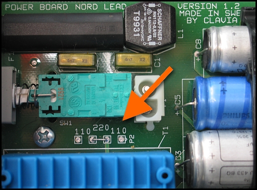
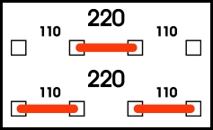
In the picture one can see the connection labelled 110-220-110. If the two inner side solder points are connected, the synth uses 220V (230V) , as in the picture. If the other connection is made, the synth uses 110V. (See the scheme) To make it usable to 110V, remove the connection and make (solder) the connection outmost left to the inner left and inner right to the outmost right. (See picture) Beware! Both 110 connections have to be made in the 110 configuration!
Of course to make a 110V synth working on 220V do it the other way around.
If you feel bad about this bring your synth to the repair shop. Just realize it would round up there anyway if you're to nervous and fail to do a proper job...
| Description: |
| Synths before 2000 (This one is 220V) |
|
| Filesize: |
181.6 KB |
| Viewed: |
108846 Time(s) |
|
| Description: |
|
| Filesize: |
16.03 KB |
| Viewed: |
108846 Time(s) |
|
Last edited by Wout Blommers on Fri Oct 24, 2008 12:30 pm; edited 5 times in total |
|
|
Back to top
|
|
 |
Wout Blommers

Joined: Sep 07, 2003
Posts: 4529
Location: The Hague - The Netherlands
Audio files: 123
G2 patch files: 12
|
|
|
Back to top
|
|
 |
Wout Blommers

Joined: Sep 07, 2003
Posts: 4529
Location: The Hague - The Netherlands
Audio files: 123
G2 patch files: 12
|
 Posted: Thu Oct 23, 2008 7:21 am Post subject:
110-115V to 220-230V or visa versa Posted: Thu Oct 23, 2008 7:21 am Post subject:
110-115V to 220-230V or visa versa
Subject description: Close again! |
  |
|
Close the synth again and replace all screws, doing the two at the bottom at last, of course!  |
|
|
Back to top
|
|
 |
Wout Blommers

Joined: Sep 07, 2003
Posts: 4529
Location: The Hague - The Netherlands
Audio files: 123
G2 patch files: 12
|
 Posted: Thu Oct 23, 2008 7:29 am Post subject:
110-115V to 220-230V or visa versa Posted: Thu Oct 23, 2008 7:29 am Post subject:
110-115V to 220-230V or visa versa
Subject description: Changing the fuse |
  |
|
The fuse has to be changed too.
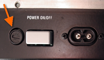
At the left of the On/Off switch is a screw, which closes the fuse holder. (See picture) Unscrew this gently (anti-clockwise), because there's a spring inside which can launch what's inside the tube. Replace the fuse itself, using the next values:
Until the year 2000
115/125V 200mA (300mA?)
or
230/250V 100mA
Since the year 2000
115/125V 250mA
or
230/250V 125mA
Close the holder.
| Description: |
|
| Filesize: |
75.61 KB |
| Viewed: |
108841 Time(s) |
|
| Description: |
| What are we talking about...? |
|
| Filesize: |
63.15 KB |
| Viewed: |
108745 Time(s) |

|
Last edited by Wout Blommers on Sun Oct 26, 2008 4:15 pm; edited 7 times in total |
|
|
Back to top
|
|
 |
Wout Blommers

Joined: Sep 07, 2003
Posts: 4529
Location: The Hague - The Netherlands
Audio files: 123
G2 patch files: 12
|
|
|
Back to top
|
|
 |
Wout Blommers

Joined: Sep 07, 2003
Posts: 4529
Location: The Hague - The Netherlands
Audio files: 123
G2 patch files: 12
|
 Posted: Sat Feb 07, 2009 10:56 am Post subject:
A related topic about Power supplies (NordLead3) Posted: Sat Feb 07, 2009 10:56 am Post subject:
A related topic about Power supplies (NordLead3) |
  |
|
Last edited by Wout Blommers on Mon Feb 09, 2009 5:09 am; edited 1 time in total |
|
|
Back to top
|
|
 |
Praise the Nord

Joined: Jan 29, 2009
Posts: 4
Location: (in loco parentheses)
|
 Posted: Mon Feb 09, 2009 4:04 am Post subject:
110-115V to 220-230V Posted: Mon Feb 09, 2009 4:04 am Post subject:
110-115V to 220-230V |
  |
|
Thanks Wout for detailing the process for Nord Lead/Wave.
I recently bought a U.S. Nord Electro 2 for use in Ireland, so a voltage conversion was required (115V to 230V).
Rather than shell out €45+ for an adaptor/transformer, I used the above tutorial, and the whole process cost less than €5.
In case anyone was wondering how to do the same, here's the 115V to 230V process in detail for the Nord Electro 2 - 73 key.
Usual caveat applies: This worked for me. If it doesn't work for you, I am not responsible.
Aside from a Nord Electro 2 you will need:
1. 1 x 125mA 230V fuse (Slow blow)
2. 1 x U.S.-to-U.K. travel adaptor, or, if you know what you're doing, a U.K. plug.
Incidentally, if you live in Europe, this process is exactly the same, you just need a different plug at the end.
3. Tools - phillips and flat-head screwdriver. Wire cutters/strippers optional.
Set the keyboard up on a stand, allowing access to the back and underside.
Disconnect all cables.
To open the case:
Remove the 9 screws along the edges (pictured).
Remove the 2 remaining screws underneath (not pictured). These are the only two screws not in line with others.
Take care not to damage the screw heads.
Carefully raise the top of the keyboard, holding at the sides. Pivot as if hinged at the back of the board.
Special care should be taken not to damage the ribbon cable connecting the cover to the circuits inside.
| Description: |
11 screws total - all Phillips head.
5 along the back.
4 along the sides.
2 underneath. |
|
| Filesize: |
113.87 KB |
| Viewed: |
1482 Time(s) |
| This image has been reduced to fit the page. Click on it to enlarge. |

|
Last edited by Praise the Nord on Mon Feb 23, 2009 4:30 am; edited 2 times in total |
|
|
Back to top
|
|
 |
Praise the Nord

Joined: Jan 29, 2009
Posts: 4
Location: (in loco parentheses)
|
 Posted: Mon Feb 09, 2009 4:25 am Post subject:
110-115V to 220-230V Posted: Mon Feb 09, 2009 4:25 am Post subject:
110-115V to 220-230V |
  |
|
Replacing the fuse:
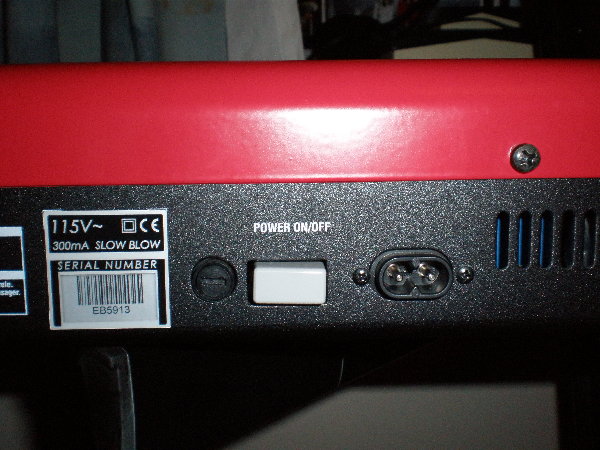
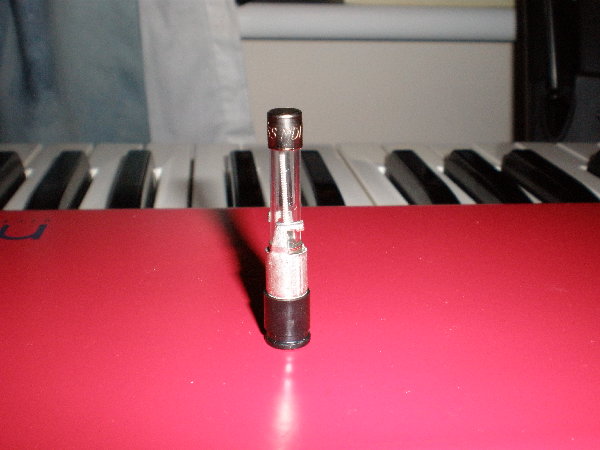
Locate the fuse holder on the back of the keyboard, just left of the power switch - see picture.
Using a flat head screwdriver, gently open the fuse holder: a fraction of a turn should release the holder, which can then be removed.
For this conversion (115V to 230V) the old fuse (250mA) must be replaced with one rated for half the current (125mA).
The Electro 2 takes 1¼" (31mm) fuses, see picture below.
I had trouble locating the fuses, so I had to order online, leaving me with 9 more than I needed  . .
If you have the same trouble, pm me and I'll post you one. 
And it may seem stupid, but glass fuses will break if you're careless.
I found that out the hard way when I dropped one on a tiled floor 
Anyway, replace your fuse and you're ready to switch voltages inside the board.
| Description: |
| Back of keyboard showing fuse holder. |
|
| Filesize: |
1.52 MB |
| Viewed: |
1725 Time(s) |
| This image has been reduced to fit the page. Click on it to enlarge. |
|
| Description: |
|
| Filesize: |
1.51 MB |
| Viewed: |
1749 Time(s) |
| This image has been reduced to fit the page. Click on it to enlarge. |
|
|
|
|
Back to top
|
|
 |
Praise the Nord

Joined: Jan 29, 2009
Posts: 4
Location: (in loco parentheses)
|
 Posted: Mon Feb 09, 2009 4:34 am Post subject:
110-115V to 220-230V Posted: Mon Feb 09, 2009 4:34 am Post subject:
110-115V to 220-230V |
  |
|
Switching voltages.
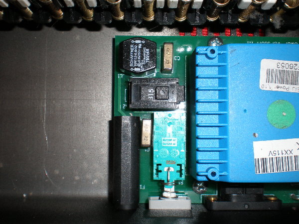
Locate the onboard switch beside the black plastic fuse-housing - see picture.
Flick the switch from 115V to 230V!
Couldn't be easier, and much respect to Clavia for including the voltage switch.
This done, it's time to close up the case.
I found it easiest to replace the 5 at the back first, followed by the 4 end screws, then tackle the underside.
Now you have a complete Nord once again.
Time to sort out your power cable.
| Description: |
|
| Filesize: |
1.57 MB |
| Viewed: |
1573 Time(s) |
| This image has been reduced to fit the page. Click on it to enlarge. |
|
| Description: |
|
| Filesize: |
1.56 MB |
| Viewed: |
1455 Time(s) |
| This image has been reduced to fit the page. Click on it to enlarge. |

|
|
|
|
Back to top
|
|
 |
Praise the Nord

Joined: Jan 29, 2009
Posts: 4
Location: (in loco parentheses)
|
 Posted: Mon Feb 09, 2009 4:42 am Post subject:
110-115V to 220-230V Posted: Mon Feb 09, 2009 4:42 am Post subject:
110-115V to 220-230V |
  |
|
If you prefer using a U.S.-to-U.K. converter, simply plug in your cable and off you go!
If, however, you don't mind cutting the cord and you've elected to go the permanent route, bear in mind the following:
U.K. standard wiring - Brown = Live! Blue = Neutral. Green/Yellow = Earth.
U.S. standard non-earthed wiring = Black = Live! White = Neutral.
That's all there is to it!
Enjoy your Nord! |
|
|
Back to top
|
|
 |
Karl
Joined: Mar 15, 2009
Posts: 2
Location: Paris
|
 Posted: Sun Mar 15, 2009 5:18 pm Post subject:
Nord Stage voltage change Posted: Sun Mar 15, 2009 5:18 pm Post subject:
Nord Stage voltage change |
  |
|
Much thanks to Wout and Praise the Nord. Without your detailed posts and pictures, I would not have been able to share this with you:
I thought somebody with a Nord Stage 76 or 88 would benefit from my discovery of how to change the voltage without a screwdriver. Thats right. I did not have to open the case.
1. Disconnect the power cord.
2. Purchase and install a new fuse appropriate for 230 volts. Its hard to find the correct fuses in Paris. The only store I found was Selectronic, a specialty electronic parts store on Place de la Nation. It cost 1 euro.
3. Cut a section from a stiff wire clothes hanger.
4. With a lamp held close to the top panel vents above the power supply, its reasonably easy to touch the sliding voltage selector and slide it to either setting. Be careful not to slip off the switch and hit another component!
5. Buy a new 2 pin power cable. I simply cut my USA pins off and installed a euro 2 pin end that fastens with screws. It cost me 0.87 centimes at Bricorama or BHV.
There you go. I'm very glad not to carry a transformer around anymore! |
|
|
Back to top
|
|
 |
Wout Blommers

Joined: Sep 07, 2003
Posts: 4529
Location: The Hague - The Netherlands
Audio files: 123
G2 patch files: 12
|
 Posted: Mon Mar 16, 2009 7:53 am Post subject:
Re: Nord Stage voltage change Posted: Mon Mar 16, 2009 7:53 am Post subject:
Re: Nord Stage voltage change |
  |
|
 Karl Karl
| Karl wrote: | | ... Be careful not to slip off the switch and hit another component! ... |
Well, it looks to me opening up the hood is much safer and more easier!

Wout |
|
|
Back to top
|
|
 |
Karl
Joined: Mar 15, 2009
Posts: 2
Location: Paris
|
 Posted: Mon Mar 16, 2009 8:28 am Post subject: Posted: Mon Mar 16, 2009 8:28 am Post subject:
|
  |
|
Right, I agree opening up the hood is safer in that it allows better access. But I was worried there wouldn't be much slack in the wires underneath the controls going to the circuit boards, so if I made a bad move opening the case I might cause damage. Clavia says if you open the case, it voids the warranty. Have a look sometime at an NS76 or NS88. You really can see the whole power supply area through the vents. Its really not that hard if you have sure hands and good near vision. Slipping is only a problem (I think) if the hanger wire is too soft and springy. Having a little curve at the end helped me get behind the slider. The other thing that really is needed is a lamp shade so you can see inside and not be blinded. I think I might try inserting a battery an LED through the vent next time, so I'd sort of use the underside of the top panel as the lamp shade.
I know this all sounds crazy, but I couldn't trust the repair shop here in Paris. It just looked too risky letting them open up my keyboard. By the looks of other clients gear piled to the ceiling, in various states of open/closed/ in progress, likely being ashed upon or espresso spilled on, and the threat of a gear avalanche with my board at the bottom seemed likely in the 7 days or so they would have had the NS in the shop. |
|
|
Back to top
|
|
 |
Oli

Joined: May 21, 2008
Posts: 250
Location: i think before i ambient
G2 patch files: 1
|
 Posted: Wed Apr 22, 2009 9:36 am Post subject: Posted: Wed Apr 22, 2009 9:36 am Post subject:
|
  |
|
Hi folk,
I just did this conversion on a Lead 1 rack I received from USA today.
One thing that should be mentioned, is that the Lead 1 rack does not have an earthed chassis.
In coutries with transformer isolated mains, this can be acceptable.
However, it does not meet the Australian Standards for electrical appliances. Australia does not use transformer isolated mains, rather a three wire / single phase safety earth system.
This is pretty common for synths which are sold worldwide.
I will likely swap the two wire flex for a three wire, and connect the chassis to the safety earth. Most mains powered synths with metal enclosures should have the chassis earthed this way.
On my G2X however, it is not so simple to earth, as it has a chassis mounted two pin power socket, rather than the grommet fitted flex used on the Lead 1 rack.
Of course, the same caveats apply to my post too. Electricity can kill, start fires, kill synths etc...
_________________
Good good study, day day up! |
|
|
Back to top
|
|
 |
blue hell
Site Admin

Joined: Apr 03, 2004
Posts: 24544
Location: The Netherlands, Enschede
Audio files: 299
G2 patch files: 320
|
 Posted: Wed Apr 22, 2009 10:41 am Post subject: Posted: Wed Apr 22, 2009 10:41 am Post subject:
|
  |
|
| Oli wrote: | In coutries with transformer isolated mains, this can be acceptable.
However, it does not meet the Australian Standards for electrical appliances. Australia does not use transformer isolated mains, rather a three wire / single phase safety earth system. |
I can not speak for the Australian situation as I do not know about the rules there ... however, in the Netherlands we do not have transformer isolated mains and yet the two wire solution (without safety ground) chosen by Clavia is perfectly acceptable as long as the appliance is double isolated and not used in wet rooms (like showers, bathrooms). The Clavia gear that I own (Nord modulars) is double isolated (which is indicated by the double square symbol on the back, one square within another, on the voltage indication label).
_________________
Jan
also .. could someone please turn down the thermostat a bit.
 |
|
|
Back to top
|
|
 |
Oli

Joined: May 21, 2008
Posts: 250
Location: i think before i ambient
G2 patch files: 1
|
 Posted: Wed Apr 22, 2009 10:59 am Post subject: Posted: Wed Apr 22, 2009 10:59 am Post subject:
|
  |
|
| Blue Hell wrote: | | ...as long as the appliance is double isolated and not used in wet rooms (like showers, bathrooms)... |
Hi,
I think you mean to write double insulated which is different from isolation. The same rule applies for Australia. I think I didn't pay due attention here, not realising that it is double insulated throughout. I can't remember clearly how the internal wiring is run.
I have a few other synths which are made in a similar fashion, which have only single insulation for the internal mains wiring, and had thought it a similar case. Probably it is fine.
Sorry for the false alarm, and thanks for pointing this out.
_________________
Good good study, day day up! |
|
|
Back to top
|
|
 |
blue hell
Site Admin

Joined: Apr 03, 2004
Posts: 24544
Location: The Netherlands, Enschede
Audio files: 299
G2 patch files: 320
|
 Posted: Wed Apr 22, 2009 11:47 am Post subject: Posted: Wed Apr 22, 2009 11:47 am Post subject:
|
  |
|
| Oli wrote: | | double insulated which is different from isolation. |
Yes, sorry, in Dutch we use the same word (isolatie) for both cases - I always forget 
_________________
Jan
also .. could someone please turn down the thermostat a bit.
 |
|
|
Back to top
|
|
 |
Oli

Joined: May 21, 2008
Posts: 250
Location: i think before i ambient
G2 patch files: 1
|
 Posted: Wed Apr 22, 2009 12:01 pm Post subject: Posted: Wed Apr 22, 2009 12:01 pm Post subject:
|
  |
|
| Blue Hell wrote: | | Oli wrote: | | double insulated which is different from isolation. |
Yes, sorry, in Dutch we use the same word (isolatie) for both cases - I always forget  |
Yeah, that's what I guessed. Even in current English usage, the literal meanings of the two words are pretty close.
_________________
Good good study, day day up! |
|
|
Back to top
|
|
 |
hardcoder
Joined: May 08, 2010
Posts: 1
Location: NYC
|
 Posted: Sat May 08, 2010 12:33 pm Post subject:
Nord Lead 3 pictures Posted: Sat May 08, 2010 12:33 pm Post subject:
Nord Lead 3 pictures |
  |
|
Thank you everyone, and Wout in particular.
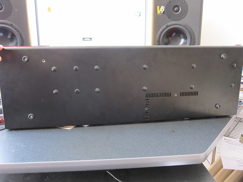
I have some pics on flickr that illustrate the screws to remove for this process for a NORD LEAD 3 (the bottom two may lead you astray). I don't have an image editor, so I used flickr's 'notes' functionality - view at http://www.flickr.com/photos/hardcoder/4589878352/in/photostream/
Please note, I interpreted "Remove everything on top of the synthesizer" as a requirement to remove knob caps - this is NOT necessary... who's the knob then? :]
 (click for others) (click for others)
Interestingly, when I asked Clavia tech support some years back about how to change the voltage, or having a tech repair person change the power supply, they said it couldn't be done. Keeping their hands clean from a legal perspective perhaps? |
|
|
Back to top
|
|
 |
Wout Blommers

Joined: Sep 07, 2003
Posts: 4529
Location: The Hague - The Netherlands
Audio files: 123
G2 patch files: 12
|
 Posted: Sat May 08, 2010 1:27 pm Post subject:
Re: Nord Lead 3 pictures Posted: Sat May 08, 2010 1:27 pm Post subject:
Re: Nord Lead 3 pictures |
  |
|
 hardcoder hardcoder
| hardcoder wrote: | | ...Interestingly, when I asked Clavia tech support some years back about how to change the voltage, or having a tech repair person change the power supply, they said it couldn't be done. Keeping their hands clean from a legal perspective perhaps? |
Maybe you asked the wrong person?
Wout |
|
|
Back to top
|
|
 |
Ndct
Joined: Sep 28, 2010
Posts: 5
Location: France
|
 Posted: Tue Sep 28, 2010 3:15 pm Post subject:
Re: 110-115V to 220-230V or visa versa Posted: Tue Sep 28, 2010 3:15 pm Post subject:
Re: 110-115V to 220-230V or visa versa
Subject description: Changing the fuse |
  |
|
Hi guys,
I need to buy 230V/125mA fuses for my future Nord Rack 3 (US model) and would like to know what are their size before placing an order? Are they "Ø5 x 20mm" ??
TIA!
| Wout Blommers wrote: | The fuse has to be changed too.
At the left of the On/Off switch is a screw, which closes the fuse holder. (See picture) Unscrew this gently (anti-clockwise), because there's a spring inside which can launch what's inside the tube. Replace the fuse itself, using the next values:
Until the year 2000
115/125V 200mA (300mA?)
or
230/250V 100mA
Since the year 2000
115/125V 250mA
or
230/250V 125mA
Close the holder. |
|
|
|
Back to top
|
|
 |
Wout Blommers

Joined: Sep 07, 2003
Posts: 4529
Location: The Hague - The Netherlands
Audio files: 123
G2 patch files: 12
|
 Posted: Thu Sep 30, 2010 8:32 am Post subject: Posted: Thu Sep 30, 2010 8:32 am Post subject:
|
  |
|
 Ndct Ndct
I completely overlooked this post... 
Yes, they are, at least, mine is...
Have you succeed in finding the right parts?
Wout |
|
|
Back to top
|
|
 |
Ndct
Joined: Sep 28, 2010
Posts: 5
Location: France
|
 Posted: Thu Sep 30, 2010 10:37 am Post subject: Posted: Thu Sep 30, 2010 10:37 am Post subject:
|
  |
|
Thanks Wout 
Yep, I ordered a few today:
- 2x "Ø5 x 20 mm 125mA Time Lag Fuse (Slo-Blo®)"
- 2x "Ø6 x 32 mm 125mA Time Lag Fuse (Slo-Blo®)"
At least I'm sure one the two models will work!
I've also ordered a Ø5 x 20 mm fuse holder + a Ø6 x 32 mm one so I'll have potential spare parts in case something funky happens.
Will post the result as soon as I receive them... |
|
|
Back to top
|
|
 |
Ndct
Joined: Sep 28, 2010
Posts: 5
Location: France
|
 Posted: Fri Oct 15, 2010 4:43 am Post subject: Posted: Fri Oct 15, 2010 4:43 am Post subject:
 Clavia Nord Rack 3 115V to 230V Clavia Nord Rack 3 115V to 230V |
  |
|
OK, here's my experience:
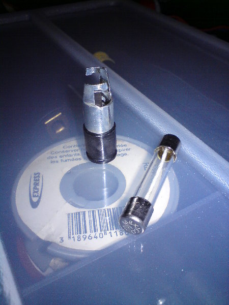
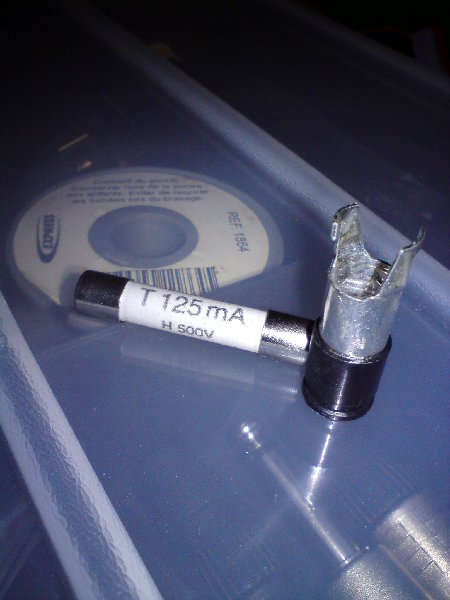
My mint US Nord Rack 3 came with a Ø6 x 32 mm 300mA (3/10A) slow blow fuse.
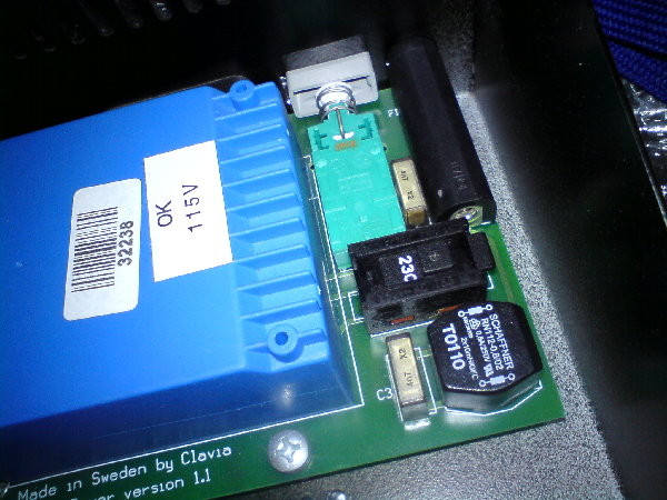
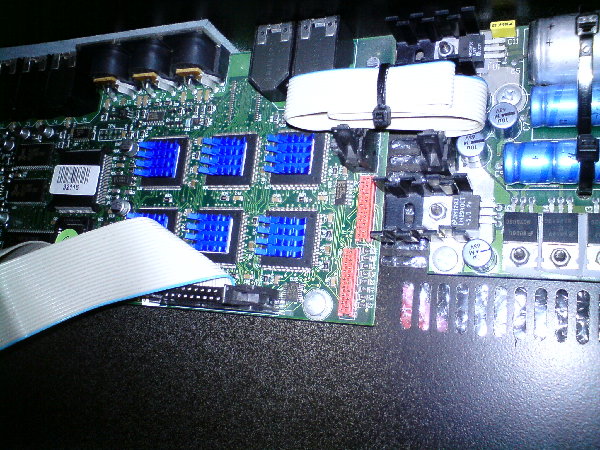
So I replaced the 300mA with a 125mA model for 230V operation [Ø6 x 32 mm 125mA Time Lag Fuse (Slo-Blo®)]. Then switched the PSU to 230V... Did some cleaning and organization under the rack... And decided to add Zalman heat sinks to the 6 120MHz DSP chips... I'm thinking about adding 1 more (bigger) heat sink to the blue power transformer to help it cool down (adhesive thermal pad needed + heat sink needed).
Finally, replaced the original power cord with a brand new one (IEC C7 connector/2 pin EURO) and powered up the Nord... Works!
Great synth!!!
| Description: |
| Nord Rack 3 US - Ø6 x 32 mm 300mA slow blow fuse |
|
| Filesize: |
781.53 KB |
| Viewed: |
1192 Time(s) |
| This image has been reduced to fit the page. Click on it to enlarge. |
|
| Description: |
| Nord Rack 3 - Ø6 x 32 mm 125mA Time Lag Fuse (Slo-Blo®) |
|
| Filesize: |
792.02 KB |
| Viewed: |
1170 Time(s) |
| This image has been reduced to fit the page. Click on it to enlarge. |
|
| Description: |
| Nord Rack 3 - PSU switch to 230V |
|
| Filesize: |
792.22 KB |
| Viewed: |
1200 Time(s) |
| This image has been reduced to fit the page. Click on it to enlarge. |
|
| Description: |
| Nord Rack 3 DSP board - Zalman heat sinks installed on the 6 Motorola DSP chips |
|
| Filesize: |
759.1 KB |
| Viewed: |
1266 Time(s) |
| This image has been reduced to fit the page. Click on it to enlarge. |
|
|
|
|
Back to top
|
|
 |
|

