| Author |
Message |
vcfool

Joined: Jun 19, 2008
Posts: 23
Location: Barcelona
|
 Posted: Tue Apr 07, 2009 7:27 am Post subject:
Roland 130 VCA PCB Design Posted: Tue Apr 07, 2009 7:27 am Post subject:
Roland 130 VCA PCB Design
Subject description: Clone for a single 130 VCA from the Roland System 100M |
  |
|
Hi,
Here's a PCB I'd like to share with you. It's one cloned VCA from the 130 module from the Roland System-100M. Rare parts that you will need are one BA6110 and one SK30A N-Channel FET transistor. I had some spare ones because I am sourcing parts to build a x0x0b0x.
First, I just cloned Roland's circuit, part by part. I don't know enough electronics to change many things. Also, someone with better experience in PCB designing, eagle cad and general electronics should have to look at this PCB: I designed it using common sense and what I learned DIYing. Of course the PCB works. I first breadboarded and tested the circuit. Then I designed, etched and populated the PCB. The module is actually finished and running.
I will not post the original Roland schematic here unless some moderator gives permission to do it. I downloaded it from curetronic site. There is a dual version PCB in there too: http://www.curetronic.com/curetrbau/neubau/130m.htm
-I used 2N3904 and 2N3906 instead of the 2SC1815Y and 2SA1015Y. These are used for the CV Lin/Exp converters so I thought it was not critical and gave it a try on a breadboard. The Lin/Exp responses still seemed pretty good to me without changing any resistor value around the transistors. But the pinout is different so if you want to use the original ones you'll have to cross legs or something.
-Of course, I also replaced the dual OpAmp for a single one. I used a TL071.
-I used a SK30A-Y, not a GR.
-I used 10uF electrolytic bipolar caps for the AC coupling (C1,C3). I don't know which will be the right polarity for them if using polarized caps. So ignore the polarity on the PCB parts layout.
-Finally some resistors were changed to match input levels, or because I didn't have the actual values. I used all 1% resistors but for R23 8K2, where I used 5% carbon because I didn't have that value on 1%. I guess you could use 5% everywhere in this VCA.
-Parts names match the first VCA from the original schematics. Extra parts are named 100 and up: Power input resistors/ferrites and decoupling caps.
I could document all this better if there's enough interest.
Thanks for reading.
Enjoy!
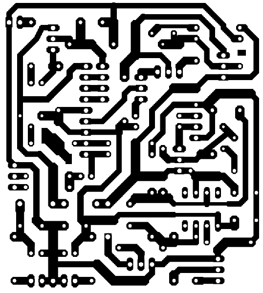
| Description: |
| Roland 130 VCA Clone - PCB Design |
|
| Filesize: |
42.39 KB |
| Viewed: |
934 Time(s) |
| This image has been reduced to fit the page. Click on it to enlarge. |
|
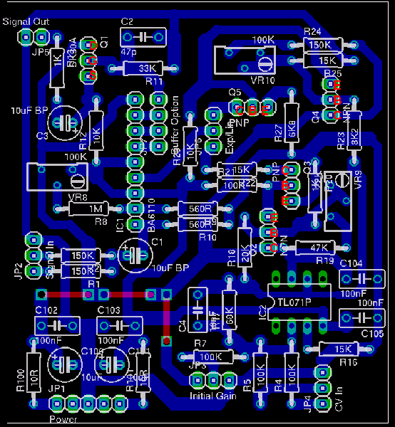
| Description: |
| Roland 130 VCA Clone - Parts Layout |
|
| Filesize: |
57.54 KB |
| Viewed: |
863 Time(s) |
| This image has been reduced to fit the page. Click on it to enlarge. |
|
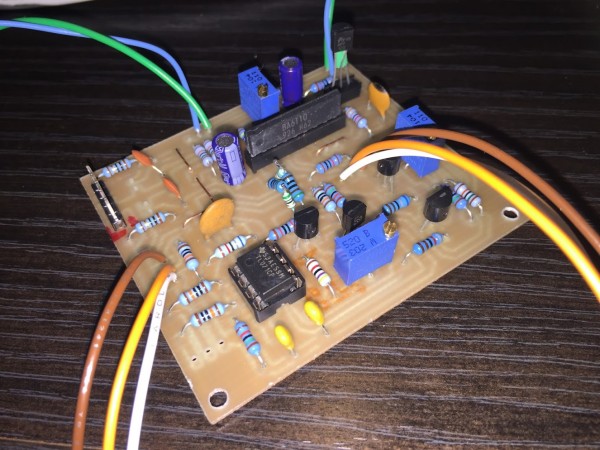
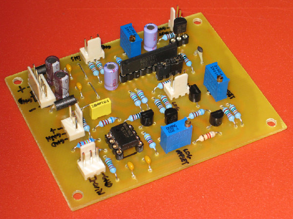
| Description: |
| Roland 130 VCA Clone - Populated PCB |
|
| Filesize: |
202.39 KB |
| Viewed: |
932 Time(s) |
| This image has been reduced to fit the page. Click on it to enlarge. |
|
Last edited by vcfool on Tue Apr 07, 2009 9:46 am; edited 1 time in total |
|
|
Back to top
|
|
 |
Sebo

Joined: Apr 27, 2007
Posts: 564
Location: Argentina
|
| Posted: Tue Apr 07, 2009 9:35 am Post subject:
|
|
|
I have some spare BA6110, I will be building one of this in the future.
Thanks a lot vcfool!!!
_________________
Sebo
---------------------------------------
My Music:
https://www.facebook.com/cosaquitos/ |
|
|
Back to top
|
|
|
Luka

Joined: Jun 29, 2007
Posts: 1003
Location: Melb.
|
| Posted: Wed Apr 08, 2009 11:07 am Post subject:
|
|
|
how does it sound?
do you get signal or cv bleed?
i also have some spare ba6110s and looking for a tight vca for my quadraphonc mixer module. i was going to use 3080 core ones but i might change if the 6110 sounds good just to use up my final 6110 stock
what is with the buffer option next to the 6110?
_________________
problemchild
melbourne australia
http://cycleofproblems.blogspot.com/
http://www.last.fm/user/prblmchild |
|
|
Back to top
|
|
|
bubblechamber

Joined: Nov 04, 2006
Posts: 280
Location: NYC
Audio files: 1
|
| Posted: Sun Apr 12, 2009 7:27 am Post subject:
|
|
|
thanks for posting this. futurelec has 2sk30 trannies for $.20, if anyone's looking for them. the tend to have a lot of weird japanese trannies.
david
_________________
You can check your anatomy all you want, and even though there may be normal variation, when it comes right down to it, this far inside the head it all looks the same. |
|
|
Back to top
|
|
|
Junk Rhythm

Joined: Jan 07, 2008
Posts: 81
Location: San Francisco, CA
|
| Posted: Sun Apr 12, 2009 10:54 am Post subject:
|
|
|
| Thanks for posting. I have some BA6110 and 2SK30 so I'll breadboard it up in the next week to check it out. |
|
|
Back to top
|
|
|
vcfool
Joined: Jun 19, 2008
Posts: 23
Location: Barcelona
|
| Posted: Sun Apr 12, 2009 7:02 pm Post subject:
|
|
|
| Luka wrote: | how does it sound?
do you get signal or cv bleed?
i also have some spare ba6110s and looking for a tight vca for my quadraphonc mixer module. i was going to use 3080 core ones but i might change if the 6110 sounds good just to use up my final 6110 stock |
I actually finished this VCA some days before posting, so I have to try it a little bit more but... sounds pretty good to me. Clean output and low background noise. No signal bleed. By adjusting the Bias offset trimmer, you can really minimize CV bleed.
I think the performance of this VCA is at least as good as other OTA VCAs I built or own. But you better try it for yourself, I am no electronics or VCA expert. If there is a special test you want me to do, just ask.
| Luka wrote: | | what is with the buffer option next to the 6110? |
Oops, I forgot to mention about that. And this is important because you need to put a bridge in JP7 to make the VCA work.
This is the last addition I made to the PCB, without trying it on the breadboard. If you look at the picture of the PCB you'll notice that there are two jumpers in there. One is connecting BA6110 Pins 6 and 7 (amp output -> buffer in), and the other is connecting Pin 8 (buffer out) to the Gate of the SK30A. Well, this didn't work that straight-forward: I got strange offsets and saturations at the output.
So you better don't use the buffer and place a strap connecting the outer pads of JP7 (BA6610 Pin 6 -> SK30A Gate). The buffer I/O pads are still there if you want to experiment. The original Roland circuit does not use the buffer anyway. I don't even know if the original BA662 has one... Is Q1 somehow doing the buffer job on this circuit?
| g.p.macklin wrote: | | Thanks for posting. I have some BA6110 and 2SK30 so I'll breadboard it up in the next week to check it out. |
Nice! Please let us know how it goes.
You all probably noticed I omitted 1 CV input, 1 Signal input and the Line Level output.
R3, R6, R14, R15 omitted.
I guess it doesn't matter that much but as I said, I didn't had some of the resistor values and I picked the nearest:
R9, R10 - 475R
R18 - 20K
R11 - 30K
R1, R2 - 150K
VR9 - 20K
And I also lowered the CV inputs:
R7 - 100K (Gain Pot)
R4 - 49K9 (Attenuated CV input)
R5 - 60K4 (Direct CV input)
Just tailor these to your needs.
Btw, found this link on another post, where you can download the complete schematics:
http://fa.utfs.org/diy/roland100m/index.html |
|
|
Back to top
|
|
|
peng

Joined: Feb 23, 2006
Posts: 111
Location: Chicago
Audio files: 2
|
| Posted: Fri Apr 17, 2009 12:41 pm Post subject:
|
|
|
| Luka wrote: | how does it sound?
do you get signal or cv bleed?
i also have some spare ba6110s and looking for a tight vca for my quadraphonc mixer module. i was going to use 3080 core ones but i might change if the 6110 sounds good just to use up my final 6110 stock |
Have you ever checked out the Mike Sims VCA design that uses both OTAs of a LM13700? It was an EDN article. Search for it.
The improvements over any 3080 VCA are enormous. Much lower SN and much MUCH lower CV feedthrough. In fact it performs as well as the VCAs I have made using a CA3280 (that's saying a lot).
Not sure how it compares to the BA6110.
p. |
|
|
Back to top
|
|
|
Luka
Joined: Jun 29, 2007
Posts: 1003
Location: Melb.
|
| Posted: Sat Apr 18, 2009 2:21 am Post subject:
|
|
|
thanks for the info gents. peng ive picked up similar info from sites like bergfotron. unfortunately i have no 13600 otas just a huge pile of 3080s and a few 6110s. now the game is all about using what i got 
ill etch up one of these boards tomorrow and check it out
is it possible to get a pdf of the layout?
_________________
problemchild
melbourne australia
http://cycleofproblems.blogspot.com/
http://www.last.fm/user/prblmchild |
|
|
Back to top
|
|
|
jbeuckm

Joined: Nov 30, 2008
Posts: 165
Location: Stockholm
Audio files: 9
|
|
|
Back to top
|
|
|
cslammy
Joined: Apr 27, 2018
Posts: 206
Location: USA
Audio files: 1
|
| Posted: Sat Mar 30, 2019 9:03 am Post subject:
|
|
|
| jbeuckm wrote: | MPF102 seems to work fine, but you have to bend the legs for this layout.
Any chance I could get a copy of the Eagle files? I would like to bring the connectors over to an edge to minimize wiring.
Thanks!
Joe |
I second that...would really like to get my hands on the eagle files.
Thanks for posting.
_________________
Visit my AUDIODIWHY blog and website |
|
|
Back to top
|
|
|
|

 Forum index » DIY Hardware and Software » The layout factory