| Author |
Message |
State Machine
Janitor


Joined: Apr 17, 2006
Posts: 2810
Location: New York
Audio files: 24
|
 Posted: Wed Jul 01, 2009 2:21 pm Post subject:
Digital Clock made with discrete Transistor/Diode Logic Posted: Wed Jul 01, 2009 2:21 pm Post subject:
Digital Clock made with discrete Transistor/Diode Logic
Subject description: I could not resist getting this Kit ... |
  |
|
I have always had a fascination for time pieces. Especially for electronic ones designed using digital logic. I had worked part time as an engineer and designed in a "smart clock" digital timer and clock module for a garage door opener system using a microcontroller and a few hundred lines of assembly code and even though I use these modern methods, I still am fascinated with design methods of yesteryear. Continuing my fascination with digital time pieces early on in my career, many years ago I designed a digital clock using bunch of MSI TTL logic IC's which were all crammed onto a 4" x 6" vector prototype board. I am a sucker for anything nostalgic and the latest offering by "Nuts and Volts" magazine really sucked me into this one and I ended up purchasing the kit today that they offer on their store
The feature article in the new July 2009 magazine describes a 12 hour format digital clock that is designed using what is considered a very old and outdated logic by today's standards ...... diode/transistor logic.
Why bother doing anything like this you ask? Well doing a clock design with nearly 200 transistors and over 550 diodes is no small feat, and, it really gets you thinking of just how a toggle type or "T" flip flop (TFF) "really" works using crossed coupled BJT transistors and current steering diodes to facilitate the toggle action. Or how to design a transistor based comparator with hysteresis or wave shapers. It gets you thinking "inside the box" and gets you past that "black box" mentality. Of course, you would be laughed out of your design department using this methodology and normally you would be using integrated circuits or programmable logic for your designs BUT for hobby purposes and understanding logic circuits at the transistor level, you can't beat these sorts of projects.
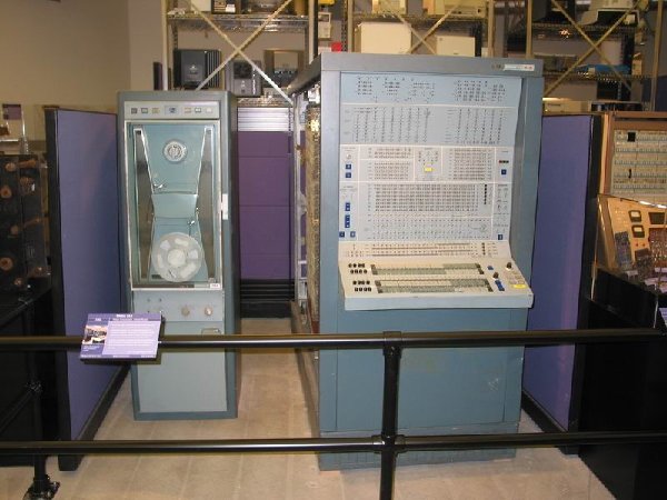
Some early computers that used this very logic design technology were the Philco 212 shown below and the IBM System 360 series. Also, don;t forget the TX-2 computer, and the sketchpad drawing programs, that was built using discrete transistor/diode logic circuits, at Lincoln Labs. It really was a precursor to modern CAD drawing systems.
What next? Well, going even further back, how about a digital clock made with vacuum tubes? I am not willing to go that far but it really makes you appreciate ENIAC or Joniac series of mainframe computers with 1000's of tubes!!! The ENIAC computer, used flip-flops composed of vacuum tubes enabled the first computer to represent numbers electronically.
Here are the links to the N&V project ...
http://www.nutsvolts.com/
http://store.nutsvolts.com/product.php?productid=16868&cat=0&page=1
Bill
| Description: |
|
| Filesize: |
1017.78 KB |
| Viewed: |
401 Time(s) |
| This image has been reduced to fit the page. Click on it to enlarge. |

|
| Description: |
|
| Filesize: |
69.2 KB |
| Viewed: |
276 Time(s) |
| This image has been reduced to fit the page. Click on it to enlarge. |
|
| Description: |
|
| Filesize: |
217.14 KB |
| Viewed: |
269 Time(s) |
| This image has been reduced to fit the page. Click on it to enlarge. |

|
|
|
|
Back to top
|
|
 |
Inventor
Stream Operator

Joined: Oct 13, 2007
Posts: 6221
Location: near Austin, Tx, USA
Audio files: 267
|
| Posted: Wed Jul 01, 2009 2:50 pm Post subject:
|
|
|
Bill,
They taught us DTL in school briefly for historical reasons, interesting project.
I made a clock for my master's thesis. It was a ring oscillator extended into a mesh form. The idea was to lower clock skew so faster processor speeds would be possible. The idea never took off but it was interesting. Provided multiphase clocks across the chip with distributed aggregation. Tick Tock goes the clock!
Les
_________________
"Let's make noise for peace." - Kijjaz |
|
|
Back to top
|
|
|
iceowl

Joined: Dec 12, 2008
Posts: 44
Location: Silicon Valley, California
|
| Posted: Wed Jul 01, 2009 3:23 pm Post subject:
|
|
|
I've built 3 or 4 of their Russian Nixie Tube clock kits. Every time I finish one and put it in a nice case and set it up in my house, one of my relatives scams it from me and I have to build another one.
It's an easy build. The design is somewhat of a digital "cheat" -- uses a PIC to generate the timing pulses & state. Everything else is analog (would have to be).
But there's nothing quite as fun as a couple hundred volts on a tiny circuit board without any accompanying cussing, smoke, and sparks.
Now this kit sounds like just the sort of : slam-your-head-into-the-wall-as-hard-as-you-can project that warrants extreme investigation. 1200+ parts to do what you could reproduce in one 8-pin IC - well, I agree with the cover of the magazine. It is a terminal force that cannot be resisted. I'm pulling out my credit card as we speak.... |
|
|
Back to top
|
|
|
andrewF

Joined: Dec 29, 2006
Posts: 1176
Location: australia
Audio files: 4
|
| Posted: Wed Jul 01, 2009 4:38 pm Post subject:
|
|
|
all tube clock?
you could do one of these -

here |
|
|
Back to top
|
|
|
State Machine
Janitor
Joined: Apr 17, 2006
Posts: 2810
Location: New York
Audio files: 24
|
|
|
Back to top
|
|
|
Tasmanian Alkaloid

Joined: Jun 29, 2008
Posts: 116
Location: Isle De Mort
|
| Posted: Thu Jul 02, 2009 7:17 pm Post subject:
|
|
|
| andrewF wrote: | all tube clock?
you could do one of these -
here |

What an incredible thing that is!!! |
|
|
Back to top
|
|
|
State Machine
Janitor
Joined: Apr 17, 2006
Posts: 2810
Location: New York
Audio files: 24
|
| Posted: Fri Jul 03, 2009 7:52 am Post subject:
|
|
|
| Quote: | They taught us DTL in school briefly for historical reasons, interesting project.
I made a clock for my master's thesis. It was a ring oscillator extended into a mesh form. The idea was to lower clock skew so faster processor speeds would be possible. The idea never took off but it was interesting. Provided multiphase clocks across the chip with distributed aggregation. Tick Tock goes the clock! |
Interesting Les. Clock skew control is a major hurdle in large modern gate array designs but has been dealt with using what are called DLL or DCM's in Xilinx devices. The DCM, for digital clock manager, will allow an external clock as it's input and then provide phase alignment to ALL blocks across the chip so that timing uncertainties won't arise in synchronous designs, which should all be BTW  With a DCM, you can also tweak the phase as you wish also. In big designs using FPGA's, the most common method is RTL design, or, register transfer logic. As each operation is completed in a particular block of logic, say a multiply, the data then moves onto the next block via a register on a clock event. Now everything is timed synchronously to a single master clock and all clock edges will be phase aligned across the chip when the DCM is used. With a DCM, you can also tweak the phase as you wish also. In big designs using FPGA's, the most common method is RTL design, or, register transfer logic. As each operation is completed in a particular block of logic, say a multiply, the data then moves onto the next block via a register on a clock event. Now everything is timed synchronously to a single master clock and all clock edges will be phase aligned across the chip when the DCM is used.
I wont get into user "timing" constraints and all since it's beyond the scope of this thread ....  Besides, I may bore you to death .... I now I bore Robin when I get going .... Besides, I may bore you to death .... I now I bore Robin when I get going ....
Bill |
|
|
Back to top
|
|
|
|

 Forum index » DIY Hardware and Software
