| Author |
Message |
Lorenzo

Joined: Nov 09, 2008
Posts: 375
Location: Trieste - Italy
|
 Posted: Thu Sep 17, 2009 4:27 am Post subject:
Simple LFO schematics?!? Posted: Thu Sep 17, 2009 4:27 am Post subject:
Simple LFO schematics?!? |
  |
|
hallo,
I'm looking for a simple (... but sweet) LFO
I found some 555 schematics ... but
I would like to run it +-12 or +-15
could you link me an LFO schematics ?
thanks!
_________________
Yes!
Oh Yeah!
Wow! |
|
|
Back to top
|
|
 |
fonik

Joined: Jun 07, 2006
Posts: 3950
Location: Germany
Audio files: 23
|
|
|
Back to top
|
|
|
Lorenzo
Joined: Nov 09, 2008
Posts: 375
Location: Trieste - Italy
|
| Posted: Thu Sep 17, 2009 4:48 am Post subject:
|
|
|
Gulp... only 5 minutes... You win the price... 
Thanks
_________________
Yes!
Oh Yeah!
Wow! |
|
|
Back to top
|
|
|
Dave Kendall

Joined: May 26, 2007
Posts: 421
Location: England
Audio files: 3
|
|
|
Back to top
|
|
|
Tim Servo

Joined: Jul 16, 2006
Posts: 924
Location: Silicon Valley
Audio files: 11
|
| Posted: Thu Sep 17, 2009 9:58 pm Post subject:
|
|
|
Several different LFO schemos here:
http://electro-music.com/forum/topic-32372.html
Including my 8K LFO and a couple of different waveshapers (I mention it because it was my own design and it's kinda nifty) 
Tim (I like LFOs) Servo |
|
|
Back to top
|
|
|
Lorenzo
Joined: Nov 09, 2008
Posts: 375
Location: Trieste - Italy
|
|
|
Back to top
|
|
|
thundarr
Joined: Jun 07, 2009
Posts: 124
Location: Newcastle upon Tyne
|
| Posted: Tue Sep 22, 2009 9:20 am Post subject:
|
|
|
Yeah, that should work fine... From what I can see that looks like a relaxation oscillator, switch S1 is your ramp/sawtooth selection switch, R5 is your frequency pot, and the chip is a dual op-amp (TL082 or similar)
Not entirely sure what switch S2 does, it changes the capacitance on the feedback loop of one of the op-amps, probably for signal shaping, I'd imagine.
It would help if we knew the values for the parts, but that circuit should oscillate at least.
EDIT: It's a very similar circuit to the one Dave Kendall has posted above.
_________________
Heavy psychedelic rock
http://www.myspace.com/landbong
Meandering ambient drone doom
http://www.myspace.com/trollmannavildtoppberg |
|
|
Back to top
|
|
|
thundarr
Joined: Jun 07, 2009
Posts: 124
Location: Newcastle upon Tyne
|
|
|
Back to top
|
|
|
Lorenzo
Joined: Nov 09, 2008
Posts: 375
Location: Trieste - Italy
|
| Posted: Tue Sep 22, 2009 1:18 pm Post subject:
|
|
|
| thundarr wrote: |
It would help if we knew the values for the parts, but that circuit should oscillate at least.
EDIT: It's a very similar circuit to the one Dave Kendall has posted above. |
| thundarr wrote: | Ahh, it's Ray's ramp and sawtooth LFO!
|
oh. sorry... 
the schematic is the "Super Simple Ramp and Sawtooth LFO" from the link that Fonik posted above:
http://www.musicfromouterspace.com/analogsynth/NewAugustRampLFO.html
Thank you for help me... tomorrow I will start to a
assemble it.
_________________
Yes!
Oh Yeah!
Wow! |
|
|
Back to top
|
|
|
Lorenzo
Joined: Nov 09, 2008
Posts: 375
Location: Trieste - Italy
|
| Posted: Mon Sep 28, 2009 4:02 am Post subject:
|
|
|
hallo...
I cannot see the right value for D1 and D2 ... can I use 1n4148 ?
_________________
Yes!
Oh Yeah!
Wow! |
|
|
Back to top
|
|
|
Sound
Joined: Jun 06, 2006
Posts: 842
Audio files: 1
|
| Posted: Mon Sep 28, 2009 4:27 am Post subject:
|
|
|
I think yes. They decide the direction of the saw, blocking the positive or the negative. By the way you can try it.
Regards Lorenzo. |
|
|
Back to top
|
|
|
Lorenzo
Joined: Nov 09, 2008
Posts: 375
Location: Trieste - Italy
|
| Posted: Mon Sep 28, 2009 2:35 pm Post subject:
|
|
|
Thank you very much!
_________________
Yes!
Oh Yeah!
Wow! |
|
|
Back to top
|
|
|
ogg

Joined: Sep 30, 2009
Posts: 10
Location: UK
|
| Posted: Sat Oct 03, 2009 5:11 am Post subject:
|
|
|
| Dave Kendall wrote: | ...
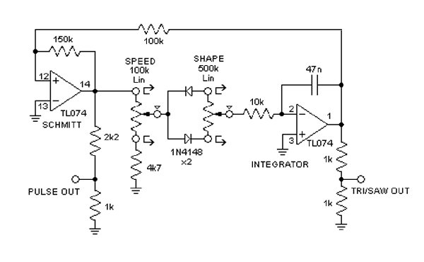
The pic below shows a cut-down version for breadboarding if you just want pulse, and a variable saw to TRI to Ramp wave. Only a dual OPamp (TL072) is needed for a single LFO.
|
Hi, I've built this circuit in a simulation online here but it's not working. It seems to me that there's no power going into it - unless the power to the op amps should be driving the whole circuit? I can't tell if it's a simulator or circuit issue.
I'm also not sure if those speed and shape variable resistors are standard pots or if the circular connections and arrows mean that other signals are entering there?
I hope you don't mind me putting it online, let me know if you do and I can take it down. (I will email Ken too). I've credited you both and linked to this thread.
Cheers,
Ollie |
|
|
Back to top
|
|
|
slacker
Joined: Nov 18, 2007
Posts: 301
Location: England
Audio files: 11
G2 patch files: 1
|
| Posted: Sat Oct 03, 2009 7:17 am Post subject:
|
|
|
I've just had a quick look at it and it's a simulator problem. I'm not an expert on simulators but I think the problem is caused by them using ideal components, and the fact that it's not simulating the effect of actually turning the power on. If you look at the voltages the output of the integrator is at 0 volts so the + input of the Schmitt is as well. The Schmitt will only do what it is supposed to if the voltage on it's 2 inputs are different, as they are both 0 volts, because the - input is connected to ground it won't do anything.
In the real world the effect of powering the circuit up plus things like the integrator capacitor charging up would cause the circuit to start up.
Something like that anyway, someone else can probably give a better explanation.
You can can make this circuit work by disconnecting the negative input of the schmitt trigger from ground and connecting it to a 1volt voltage source instead. That way when the simulation starts the 2 inputs are at different voltages so the Schmitt will work.
Nice site by the way, I've seen that falstad thing before but I didn't realise you could make your own circuits with it. |
|
|
Back to top
|
|
|
ogg
Joined: Sep 30, 2009
Posts: 10
Location: UK
|
| Posted: Sat Oct 03, 2009 9:34 am Post subject:
|
|
|
Thank you 
I've added your fix to the circuit and put it on the site. |
|
|
Back to top
|
|
|
Tim Servo
Joined: Jul 16, 2006
Posts: 924
Location: Silicon Valley
Audio files: 11
|
Posted: Sat Oct 03, 2009 11:31 am Post subject:
Subject description: Ramp/Saw LFO mods |
|
|
| thundarr wrote: | Ahh, it's Ray's ramp and sawtooth LFO!
Yeah, that looks just right |
A couple of suggestions for that LFO: If you used a SPDT center off switch for the ramp/saw switch, you could take both diodes out of the circuit when the switch was in the center position. This would give you a triangle wave, although the frequency would be 1/2 the saw/ramp freq. Still, another wave available just by using a slightly different switch. Also, you should be able to tap a square wave off pin 7 of IC1. The square at that point would be hotter than the standard +/-5V level, so you'd want to use a couple of resistors to knock the level down a bit. Ideally, you might want to separately buffer that square, but you could probably get by without it. Note that I haven't tested these, but they should be simple mods to try.
Tim (simple is my middle name... not really, but it sounded good) Servo |
|
|
Back to top
|
|
|
MC1495
Joined: Mar 24, 2009
Posts: 19
Location: baltimore
|
| Posted: Thu Aug 11, 2011 2:27 am Post subject:
|
|
|
Regarding the simple LFO schematic at the top of the page (simple osc2.jpg - I think the first time I saw this was Ian Fritz's schematic for ElectroNotes?) -
Has anyone given any thought to making the symmetry adjustable by voltage control? The only solution I can come up with is some sort of cross-fading circuit - but maybe there is something more direct? .. |
|
|
Back to top
|
|
|
JovianPyx

Joined: Nov 20, 2007
Posts: 1988
Location: West Red Spot, Jupiter
Audio files: 224
|
|
|
Back to top
|
|
|
|

 Forum index » DIY Hardware and Software