| Author |
Message |
ChrisR

Joined: Feb 22, 2009
Posts: 24
Location: Dark side of the room
|
 Posted: Sun Sep 20, 2009 10:36 am Post subject:
Broken Dynacord TAM 19 - suggestions needed Posted: Sun Sep 20, 2009 10:36 am Post subject:
Broken Dynacord TAM 19 - suggestions needed
Subject description: Also looking for a service manual. |
  |
|
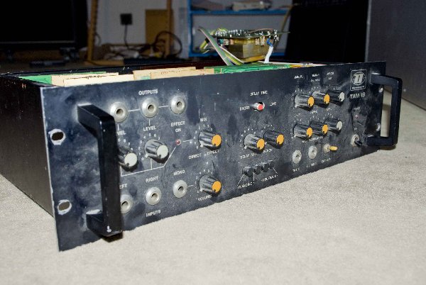
Ok, so i just got a Dynacord TAM 19 (Time Axis Manipulation System) for super cheap at a fleamarket.
The top side of the case has some rust on it, and the pots' movement feels like they're done.
To my surprise it looks quite ok on the inside, no missing parts or signs of damage.
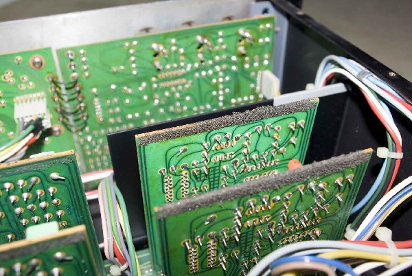
However, the foam which holds the vertically mounted PCBs in place (when the unit is closed) has completely degenerated, leaving lots of stains on the PCBs and parts. How should i go about removing that? Never done that before...
Also, could the remains of the foam cause shorts in the circuit?
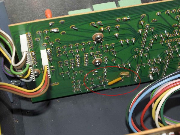
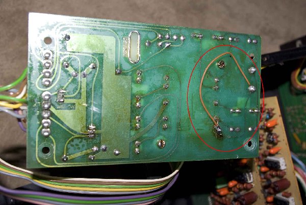
It looks like someone has done a repair job on this one. The PSU has a wire jumper (and a missing fuse!), and on one of the PCBs two solder pads where removed and replaced with wire jumpers. Gonna have to check this.
In conclusion, this doesn't look like it's a hopeless case. I'm going to completely disassemble and clean it first, and then try to power it up.
What should i use to clean up the remains of the foam?
I'm also looking for a (service) manual, or maybe even some schematics. Anyone?
Thanks,
Chris
| Description: |
|
| Filesize: |
321.98 KB |
| Viewed: |
274 Time(s) |
| This image has been reduced to fit the page. Click on it to enlarge. |
|
| Description: |
| Degenerated foam on the PCB's |
|
| Filesize: |
153.26 KB |
| Viewed: |
248 Time(s) |
| This image has been reduced to fit the page. Click on it to enlarge. |
|
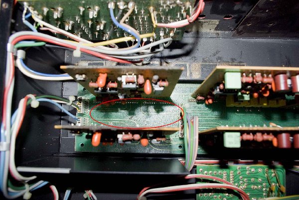
| Description: |
| Degenerated foam on the surface of the main PCB |
|
| Filesize: |
155.67 KB |
| Viewed: |
260 Time(s) |
| This image has been reduced to fit the page. Click on it to enlarge. |
|
| Description: |
| Someone f'ed up some solder pads |
|
| Filesize: |
145.48 KB |
| Viewed: |
252 Time(s) |
| This image has been reduced to fit the page. Click on it to enlarge. |
|
| Description: |
| Nice repair job on the PSU |
|
| Filesize: |
121.71 KB |
| Viewed: |
228 Time(s) |
| This image has been reduced to fit the page. Click on it to enlarge. |
|
|
|
|
Back to top
|
|
 |
ChrisR
Joined: Feb 22, 2009
Posts: 24
Location: Dark side of the room
|
| Posted: Wed Sep 23, 2009 4:21 am Post subject:
|
|
|
Ok, i'm rephrasing my question:
What's the best way to clean a circuit board from old, degenerated foam?
this stuff is very sticky, so i can't just brush it away.
I have no clue, please tell me  |
|
|
Back to top
|
|
|
Uncle Krunkus
Moderator

Joined: Jul 11, 2005
Posts: 4761
Location: Sydney, Australia
Audio files: 52
G2 patch files: 1
|
| Posted: Wed Sep 23, 2009 4:56 am Post subject:
|
|
|
Brush and/or wipe it away as much as you can, then I'd use some CRC contact cleaner to get rid of the rest of it. Any hydrocarbon based cleaning spray would probably do it too.
Check for leaking electrolytic capacitors while you're cleaning, especially around the PSU, and replace them before powering up.
BTW, what is a Dynacord TAM19? (I should google it hey?)
_________________
What makes a space ours, is what we put there, and what we do there. |
|
|
Back to top
|
|
|
ChrisR
Joined: Feb 22, 2009
Posts: 24
Location: Dark side of the room
|
| Posted: Wed Sep 23, 2009 4:46 pm Post subject:
|
|
|
| Uncle Krunkus wrote: | | BTW, what is a Dynacord TAM19? (I should google it hey?) |
You probably wouldn't find that much - i did not (so far).
It's an analog stereo Flanger/Chorus thingie from the late 70ies. Has some tad1022 in it. So far i wasn't able to find a manual for it, but it looks like there's an envelope follower, a tri LFO and a CV input for modulation purposes. There's also a CV out jack which carries the tri LFO.
I'd really like to get this thing running.
| Uncle Krunkus wrote: | | Brush and/or wipe it away as much as you can, then I'd use some CRC contact cleaner to get rid of the rest of it. Any hydrocarbon based cleaning spray would probably do it too. |
Thanks. 
| Uncle Krunkus wrote: | | Check for leaking electrolytic capacitors while you're cleaning, especially around the PSU, and replace them before powering up. |
The process of checking for a leaking cap would involve applying a voltage across it, turning the voltage off and then measuring how fast the voltage drops? Or something like that? I guess i'd have to desolder the cap first? |
|
|
Back to top
|
|
|
Danno Gee Ray
Joined: Sep 25, 2005
Posts: 1351
Location: Telford, PA USA
|
| Posted: Wed Sep 23, 2009 6:07 pm Post subject:
|
|
|
Check out the Realistic MG-1 sites for tips on getting rid of the foam residue. I would even consider leaving it on the surface of the PCB where it won't affect connections or solder pads. This stuff is right very gummy, I had decent luck with Isopropyl (Rubbing) Alcohol. Strong solvents might cause more damage than the gummy residue would. If it's not in a switch contact, slider, pot, or a Card edge connection, leaving it alone may be the better part of valor, at least until you know if the thing is going to work or not.
As to the Caps, It might be a good idea to wholesale replace the Electrolytics throughout. Caps that old will begin to dry up and fail. Replacing them all now will save headaches in the future.
Just my 2 cents. |
|
|
Back to top
|
|
|
Uncle Krunkus
Moderator
Joined: Jul 11, 2005
Posts: 4761
Location: Sydney, Australia
Audio files: 52
G2 patch files: 1
|
| Posted: Wed Sep 23, 2009 6:54 pm Post subject:
|
|
|
Yeah, like Danno said! 
I actually meant "leaking" as in physically exuding some kind of goop, which is the electrolyte jumping ship.
Replacing all of them after this much time would be a good idea, but, again as Danno said, I'd check whether it works or not first.
Can you disconnect the PSU and check whether it has "reasonable" outputs before you try the complete unit? While you're there, "look into" the PSU connections for the rest of the unit with your DMM set for resistance. A complete short or open circuit there would be another very handy clue before applying power. (try swapping polarity of your DMM too)
_________________
What makes a space ours, is what we put there, and what we do there. |
|
|
Back to top
|
|
|
ChrisR
Joined: Feb 22, 2009
Posts: 24
Location: Dark side of the room
|
| Posted: Thu Sep 24, 2009 4:29 am Post subject:
|
|
|
| Danno Gee Ray wrote: | | If it's not in a switch contact, slider, pot, or a Card edge connection, leaving it alone may be the better part of valor, at least until you know if the thing is going to work or not. |
That is probably the best way to go about it.
I was thinking that the foam residue may cause some weird electrical side effects, therefore i wanted to get rid of it.
| Uncle Krunkus wrote: | | Can you disconnect the PSU and check whether it has "reasonable" outputs before you try the complete unit? While you're there, "look into" the PSU connections for the rest of the unit with your DMM set for resistance. A complete short or open circuit there would be another very handy clue before applying power. (try swapping polarity of your DMM too) |
Yes, the PSU is on it's own PCB (there are *12* PCB's in there!). It'll be the first thing i check.
Great idea, looking into the power connections of the other boards, checking for resistance. Thanks for the good advice!
| Danno Gee Ray wrote: | | As to the Caps, It might be a good idea to wholesale replace the Electrolytics throughout. Caps that old will begin to dry up and fail. Replacing them all now will save headaches in the future. |
Yes, i'll do that.
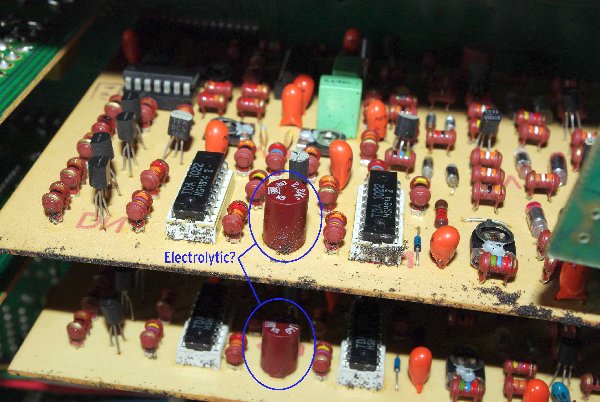
However, there are some caps (see attached pic) where i'm not sure if they're electrolytics or not. Are they?
| Description: |
| Are the big brown thingies electrolytic capacitors? |
|
| Filesize: |
328.67 KB |
| Viewed: |
271 Time(s) |
| This image has been reduced to fit the page. Click on it to enlarge. |
|
|
|
|
Back to top
|
|
|
Uncle Krunkus
Moderator
Joined: Jul 11, 2005
Posts: 4761
Location: Sydney, Australia
Audio files: 52
G2 patch files: 1
|
| Posted: Thu Sep 24, 2009 6:14 am Post subject:
|
|
|
Yeah, they're electrolytics.
It looks like it's got plenty of polystyrene caps as well. They are very stable and accurate. It must have been a good quality unit in it's time.
The orange blobs are tantalum caps. I think I remember they can go belly up too over time. Or was it that they tend to go short circuit when they fail?
_________________
What makes a space ours, is what we put there, and what we do there. |
|
|
Back to top
|
|
|
ChrisR
Joined: Feb 22, 2009
Posts: 24
Location: Dark side of the room
|
| Posted: Thu Sep 24, 2009 7:17 am Post subject:
|
|
|
| Uncle Krunkus wrote: | | Yeah, they're electrolytics. |
Thanks, about 20 of those in there. Not too bad.
| Uncle Krunkus wrote: | | It looks like it's got plenty of polystyrene caps as well. They are very stable and accurate. It must have been a good quality unit in it's time. |
The pic shows the two delay boards (you can see the TDA1022 in the white sockets). Each has 10 polystyrene caps. On each LFO board there are two. The LFOs are actually VCOs, btw. (external CV input!)
Yeah, i too think that this was a pretty solid piece of gear. Inter-board connections are mostly done with headers, all IC's are socketed, and someone has done a pretty good wiring job.
Like i said, there are 12 boards inside, big circuit. 
I just *have* to hear how it sounds.
| Uncle Krunkus wrote: | | The orange blobs are tantalum caps. I think I remember they can go belly up too over time. Or was it that they tend to go short circuit when they fail? |
Yeah, tantalum.
General question: What about polystyrene, wima, etc. caps? Do those too fail over time like the electrolytics?
(Sorry for the overly noob questions, btw.) |
|
|
Back to top
|
|
|
Danno Gee Ray
Joined: Sep 25, 2005
Posts: 1351
Location: Telford, PA USA
|
| Posted: Thu Sep 24, 2009 2:28 pm Post subject:
|
|
|
Electrolytics contain a semi liquid / paste inside the can that over time will leak out or dry up.
The other caps (polystyrene etc) to my knowledge do not contain an electrolyte of that nature.
I'm not sure on the tantalums however...I seem to recall a problem with some of them in Mil-Spec equipment in the 80's having a problem with leaking / corrosion. They may have been a hybrid Electrolytic though.
Any Engineers got knowledge to impart? |
|
|
Back to top
|
|
|
ChrisR
Joined: Feb 22, 2009
Posts: 24
Location: Dark side of the room
|
| Posted: Thu Sep 24, 2009 4:10 pm Post subject:
|
|
|
| Danno Gee Ray wrote: | | I'm not sure on the tantalums however...I seem to recall a problem with some of them in Mil-Spec equipment in the 80's having a problem with leaking / corrosion. They may have been a hybrid Electrolytic though. |
Wikipedia tells me that tantalum capacitors are actually of electrolytic type:
| Wikipedia wrote: | | The tantalum capacitor is a highly reliable type of electrolytic capacitor in which the dielectric is formed from a very thin anodized layer of tantalum pentoxide. |
http://en.wikipedia.org/wiki/Tantalum_capacitor
Question: Do tantalum capacitors tend do fail over time like "normal" electrolytic caps? Should they therefore be replaced in old (like 30 years old) equipment? |
|
|
Back to top
|
|
|
blue hell
Site Admin

Joined: Apr 03, 2004
Posts: 24452
Location: The Netherlands, Enschede
Audio files: 297
G2 patch files: 320
|
| Posted: Thu Sep 24, 2009 4:19 pm Post subject:
|
|
|
| Chris Rogue wrote: | | Wikipedia tells me that tantalum capacitors are actually of electrolytic type: |
Yes, but the dielectric is solid state, so no leaking at least.
_________________
Jan
also .. could someone please turn down the thermostat a bit.
 |
|
|
Back to top
|
|
|
Uncle Krunkus
Moderator
Joined: Jul 11, 2005
Posts: 4761
Location: Sydney, Australia
Audio files: 52
G2 patch files: 1
|
| Posted: Thu Sep 24, 2009 5:52 pm Post subject:
|
|
|
Based on some info I found here:
http://my.execpc.com/~endlr/reliability.html
I'd say that the smaller values of tantalum caps (<2uF) in this unit could almost universally be replaced with modern film type caps, MKTs would be fine.
Tantalums in general have some problems with inrush currents, and leakage (electrical, not physical). They even suggest that ceramics are a good option if the value needed is low enough. I wouldn't replace them with polyester, as the main concern is probably the leakage and new greencaps won't improve that by much.
Of course this is assuming that you want to re-condition this unit in a big way. Make sure it works first. It seems tants tend to fail catastrophically, so if they look good, they're probably not a problem.
_________________
What makes a space ours, is what we put there, and what we do there. |
|
|
Back to top
|
|
|
ChrisR
Joined: Feb 22, 2009
Posts: 24
Location: Dark side of the room
|
| Posted: Sun Oct 04, 2009 12:43 pm Post subject:
|
|
|
Thank you all for the input - very much appreciated!
I'm done disassembling the unit and cleaning the boards. They got an unbelieveable amount of solder flux on them. i just left it there for the time being...
I have to order some parts for the PSU, which definitely needs fixing.
Maybe i'll get the whole unit to power up then.  |
|
|
Back to top
|
|
|
tiego
Joined: May 15, 2010
Posts: 15
Location: France
|
| Posted: Mon May 17, 2010 3:07 pm Post subject:
|
|
|
Hello there
Did you manage to get the Tam working Chris?
I may grab one TAM 21 which PSU is dead i have been told.
Hope I can replace it, and that the fuses did their job...
Sonically,
Tiego |
|
|
Back to top
|
|
|
|

 Forum index » DIY Hardware and Software
