| Author |
Message |
jumunius
Joined: Apr 19, 2010
Posts: 346
Location: San Francisco, CA
Audio files: 13
|
 Posted: Mon Aug 15, 2011 12:43 am Post subject: Posted: Mon Aug 15, 2011 12:43 am Post subject:
|
  |
|
So, continuing the conversation with myself, I have completed two mods, with samples:
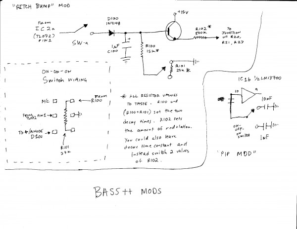
1) The "Pitch Bump", which is basically a very short bump in pitch roughly corresponding to the impact tone. If you've followed my monologue thus far, I have now ditched the previous scheme of using the Impact output as Shell CV. What I have now replicates the Bass++ envelope generator with fixed rather than variable values, and feeds the new envelope directly into the CV junction (R20, R21, R23) via an on-on-on switch for choosing off ("no bump"), short decay ("bump") or slightly longer decay ("big bump"). In the bass range this is now, to my ear, a strong addition. (At higher pitches the sound the sweep is more pronounced and can be a little excessive.) Where the impact sound as Thomas designed it seems a bit similar to a feature of the 808 kicks (a short click), the pitch bump sounds to me like a feature of the 909 kick (more punchy impact). Now you can have both in one device. People who have done Doug's mod already can do this, and anyone with an external envelope generator can add a short decaying envelope as CV. But lacking the panel space for Doug's extra decay pot, and for the cost of one switch, I find it nice to have this as an onboard option. And if you really want a "Bentley" modded Bass++, add both Doug's and mine, since you can use both at the same time -- one sweep will give definition to the impact while the other sweep gives the standard, more gradual sweep. There's an example of using the bump and the standard sweep at the same time in my attached mp3 file.
2) The "pip mod". I'm surprised nobody has mentioned this. It's almost not a "mod" since it comes straight from Thomas' "Theory and Operation". C7 (10nf from LM13700 pin 10 to ground) trims a "pip" out of the triangle wave in the VCO. Removing it creates a buzzier sound (a little spike at the tip of the triangle). Lowering the value only partially reduces the buzz. So I added an On-Off-On switch so I can now access the stock value of 10nf, a modified value of 1nf, and no cap. You can hear the results in my 2nd sound file as I switch from one value to the next, using all the spectrum of waveshapes from Doug's waveshaper mod over the course of the file. Note: the switching between caps causes pops and clicks -- if I ever left the switch alone you wouldn't hear any clicking, only pipping. 
Note: I found other satisfying cap values, and 500pf seemed more useful to my ear than going capless. But I decided that I could probably scale the capless one back with an LPF, whereas if I added the 500pf in place of capless, I could never get the raw buzzy quality back. (And I only had an On-Off-On switch left after the pitch bump mod.)
I should say, one very nice thing about the Quad Bass layout is that there is plenty of room to replicate and modify the circuit if you aren't building all four. I'm probably only building 2, so I can easily replicate parts of the circuit using the unused layouts. Kudos to Bill and Dan for this, it's so much easier than adding a daughterboard. I wish more tiny PCBs would come as dual or quad layouts!
I'll try to upload a schematic for these mods soon.
[ETA more cap info, clarity]
| Description: |
| Demo of the pitch bump mod. Explains itself as it goes. |
|

Download (listen) |
| Filename: |
bass++_pitchbump.mp3 |
| Filesize: |
3.92 MB |
| Downloaded: |
1689 Time(s) |
| Description: |
| Pip mod demonstration, switching between standard 10nf cap, 1nf modded value, and no cap. |
|
Download (listen) |
| Filename: |
bass++_pipmod.mp3 |
| Filesize: |
2.47 MB |
| Downloaded: |
1587 Time(s) |
|
|
|
Back to top
|
|
 |
diablojoy

Joined: Sep 07, 2008
Posts: 809
Location: melbourne australia
Audio files: 11
|
| Posted: Mon Aug 15, 2011 6:40 pm Post subject:
|
|
|
very nice mods the bump mod is really interesting
hope you will post a schematic of exactly what you did there
though i think i can nut it out from your desciption |
|
|
Back to top
|
|
|
jumunius
Joined: Apr 19, 2010
Posts: 346
Location: San Francisco, CA
Audio files: 13
|
|
|
Back to top
|
|
|
Dan Lavin

Joined: Nov 09, 2006
Posts: 649
Location: Spring Lake, Mi, USA
Audio files: 21
|
| Posted: Tue Aug 16, 2011 6:23 pm Post subject:
|
|
|
Jumunius, very nice mods. I particularly like the small pitch bump.
| Quote: | | Kudos to Bill and Dan for this, it's so much easier than adding a daughterboard. I wish more tiny PCBs would come as dual or quad layouts! |
You can probably give more credit to Bill for the quad idea. I was thinking more like 2 at the beginning, but Bill can be persuasive! The artwork wasn't that bad because after I laid out section A, I could just copy and paste then string the power lines together. Bill corrected a couple errors and added more to the silkscreen legend to finish it off.
_________________
Synth DIY since 1977! |
|
|
Back to top
|
|
|
marvkaye
Joined: Mar 14, 2011
Posts: 225
Location: Fla
|
| Posted: Thu Sep 01, 2011 12:00 pm Post subject:
|
|
|
I'm really impressed with everyone's work here... some very creative things have been shared. Thanks so much for what you guys do, it never ceases to amaze me.
I just started working on the first of my Bass++ boards, and what I thought I'd do is optimize each section to a specific percussion instrument type to make programming a bit simpler down the road. I've populated the "A" section of the first board totally stock as a sort of utility module, to retain the flexibility it offered.
I thought I'd make the first "B" section be kick drum specific and incorporate the larger cap at C2 and the waveshaper (thank you Doug, brilliant stuff) and would like to add Jumunius' "bump mod", especially since it's switchably available in a couple different amounts... very cool Jumunius. Unfortunately, I'm having a bit of a problem figuring out just what to do there, as the drawing leaves me slightly unclear on a couple things... does the drawing of the on-on-on switch at the lower left represent the 2 switches in the schematic? Also, does the whole little circuit shown at the top get parallelled into the circuit between TL072p1 and the junction of R20, 21 & 23? That would make perfect sense, but I've got the datasheet for an NKK SP3T switch and am having a really hard time understanding what's going on with it connected up as per your on-on-on switch drawing. It makes my brain hurt 
Maybe when I get back to the ranch I'll redraw the schematic and relate to the switch drawings from the datasheet... maybe it will all become clear. Hope so. I'd hate to get stuck at the first modified module... doesn't bode well for later activity, that's for sure. Thanks in advance for any assistance you care to offer.
<marv> |
|
|
Back to top
|
|
|
jumunius
Joined: Apr 19, 2010
Posts: 346
Location: San Francisco, CA
Audio files: 13
|
| Posted: Thu Sep 01, 2011 2:27 pm Post subject:
|
|
|
| marvkaye wrote: | Unfortunately, I'm having a bit of a problem figuring out just what to do there, as the drawing leaves me slightly unclear on a couple things... does the drawing of the on-on-on switch at the lower left represent the 2 switches in the schematic?"
Also, does the whole little circuit shown at the top get parallelled into the circuit between TL072p1 and the junction of R20, 21 & 23? That would make perfect sense, but I've got the datasheet for an NKK SP3T switch and am having a really hard time understanding what's going on with it connected up as per your on-on-on switch drawing. It makes my brain hurt |
Hi, glad you like it. As for the On-On-On switch, it's a C&K 7211 style switch. You can think of this like 2 on-on switches activated by a single device. Check out Scott Stites' diagram of it (but ignore "place jumper here" for this usage... handy for many other uses though). Is that at all like what you read in your datasheet?
In my usage, the 4-5-6 column turns the trigger pulse on and off (since TL072 pin1 only goes to the mod when the toggle is middle or up -- pin 6 is unconnected). The 1-2-3 column just changes the resistance to ground -- 15k or 42k depending on where the switch is positioned.
After working on a similar mod to a different module (DS8) I realized a couple things. 1) that an On-Off-On could do something similar here, with a bit of manipulation. 2) that in the EG schematic I'd adapted this from, there's a 4.7k to ground at the junction with the emitter of the 3904 -- obviously, my mod seems to work without though -- I have yet to try what difference that would make.
So in case anyone cares, to make this work with On-Off-On you can choose a fixed amount of decay (for instance, R100 could stay at the moderate 15k, or a happy medium between 15k and 42k, R101 would go away). Instead have the switch choose the amount of resistance before the CV junction. (Think of this as changing values on your sweep pot rather than your decay pot.) R102 is replaced by the On-Off-On switch, where you are switching between the moderate level of 500k, and something more aggressive like 240k or whatever sounds good. 4-5-6 on the 7211 become irrelevant in this version; when switch is in off position, there is no pitch bump cv sent to R20/R21/R23. |
|
|
Back to top
|
|
|
marvkaye
Joined: Mar 14, 2011
Posts: 225
Location: Fla
|
| Posted: Fri Sep 02, 2011 5:35 am Post subject:
|
|
|
Thanks for the explanation, Jumunius... it's a bit clearer now. After studying the data sheets for a bit, looking at Scott's drawing, and reading your explanation I think I've got it.
I find it interesting that the datasheets from C&K and NKK each treat this switch differently... NKK calls it out as a SP3T and mentions that is uses a DPDT body, while C&K keeps it in the DPDT category but footnotes it to a "Section N" of the datasheet for 3-way wiring directions. Only problem is the C&K datasheet that's readily available stops at section "F"... go figure. 
Once I tighten up my documentation I guess it's time to go ahead with section B... fun stuff. Thanks again for the assistance.
<marv> |
|
|
Back to top
|
|
|
marvkaye
Joined: Mar 14, 2011
Posts: 225
Location: Fla
|
| Posted: Thu Sep 08, 2011 7:13 pm Post subject:
|
|
|
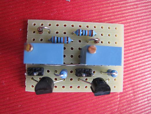
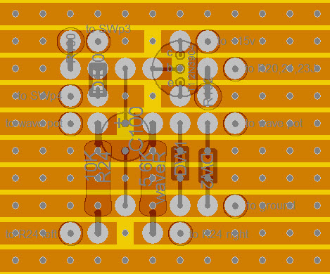
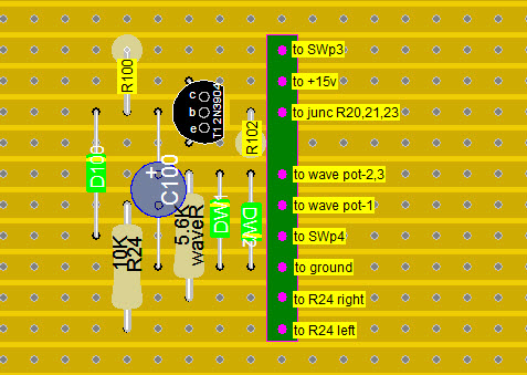
After quite a bit of head scratching trying to figure out how to incorporate my chosen mods into the "B" section of my Bass++ I think I've finally come up with a solution. As I mentioned before, I wanted this section to be my primary kick drum module, so wanted to incorporate Doug's frequency lowering mod (C2 change), plus his waveshaper and Jumunius' "pitch bump". The C2 change was easy, but how to get the other two installed and provide for the wiring to the panel neatly really had me stumped. I decided on a little stripboard daughterboard (about 0.8" square) to hold the components for both mods and provide for the panel wiring in one fell swoop.
If you look at the pictures you'll see that the bottom 4 strips handle the wave shaper mod. By moving R24 from the Bass++ PCB to the daughterboad I get to use the R24 pads both to connect the mod to the B++ and if I use headers instead of wires for the connections they would float the daughterboard above the B++ (with a little support glued in at the other end). Then again, maybe that's not such a good idea, as I'd have to unsolder it from the B++ if there's a problem that requires access to the stuff under it... maybe just use wires and secure it to the top of the LM13700 with a wire tie and some insulation between the two? Thoughts, anyone?
Moving forward, the top 3 strips make up the pitch bump mod... C100 gets its ground from the waveshaper ground strip, but other than that, all the pitch bump stuff is on the upper 3 strips.
So there's my intended solution... if any of you have a better idea, please, by all means, let me know. Unless someone tells me this is not a good solution and suggests an alternative I'll probably be soldering this up this weekend. (I'd also like to hear how other folks have incorporated their mods.... there's much to learn here, that's for sure.)
<marv>
| Description: |
| Stripboard top showing Pitch bump and waveshaper mods... thanks for sharing them, guys! |
|
| Filesize: |
97.36 KB |
| Viewed: |
65508 Time(s) |
|
| Description: |
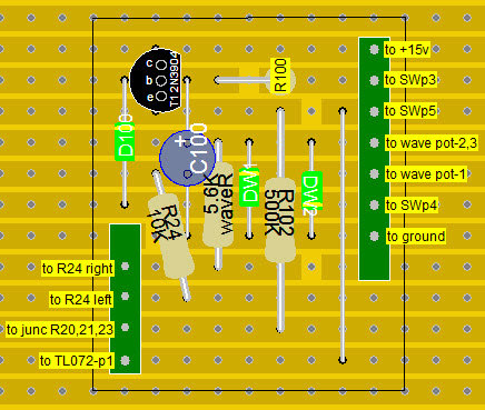
| This is the view straight through the parts, not flipped as if you were looking at the strips... just to show the breaks. I'd be happy to post or send the rear view, just ask. |
|
| Filesize: |
103.56 KB |
| Viewed: |
65508 Time(s) |
|
|
|
|
Back to top
|
|
|
jumunius
Joined: Apr 19, 2010
Posts: 346
Location: San Francisco, CA
Audio files: 13
|
| Posted: Fri Sep 09, 2011 5:21 am Post subject:
|
|
|
| marvkaye wrote: | | The C2 change was easy, but how to get the other two installed and provide for the wiring to the panel neatly really had me stumped. I decided on a little stripboard daughterboard (about 0.8" square) to hold the components for both mods and provide for the panel wiring in one fell swoop. |
Seems ok but things are a little tight in places. For example, there are a lot of trace cuts around the transistor. You might move everything to the right of the transistor over by a column or two, just to make sure you have room for soldering. Stripboard can be a little messier, easier to make solder bridges in my limited experience. Also, why not line up your wiring into columns -- you could more easily use headers to easily connect/disconnect in this case.
| Quote: | ...if I use headers instead of wires for the connections they would float the daughterboard above the B++ (with a little support glued in at the other end). Then again, maybe that's not such a good idea, as I'd have to unsolder it from the B++ if there's a problem that requires access to the stuff under it...
|
Yeah, that might be a hassle, I would recommend doing this in a way that is easier to detach. You want to be able to easily test and tweak as necessary. Plus, if you are still working on your C and D sections, you want to be able to work with the main board easily, without anything in the way. What if you decide to mod C and D? Things could get messy fast. And if you are relying on the wiring itself to hold your daughterboard in place, that sounds like a long-term stability problem, although the db will at least be light.
If you're not making all 4 voices you could do what I did and use one of the spare layouts to mount your components. The pitch bump mod could easily use the decay circuit from section D, while you fly wires to and from it under the board. But I assume you're making C and D from your description, so...
It sounds like part of the problem is you don't have an easy place to physically mount your daughterboard. It's hard to troubleshoot that without knowing what your enclosure looks like. I generally use mounting brackets made out of cheap sheet metal pieces from a hardware store, and they are big enough to attach a daughterboard off one end. Can take a pic later.
Then to connect between boards, you should probably use the same sort of interconnects on your db that the Bass++ recommends for its panel wiring. That way you can disconnect everything from the main board to work on future sections.
As for the main board, you may be able to find sufficient room to drill 4 holes (on an edge?) and mount a header there, flying wires under the board to it. More likely, you just fly wires directly to your db interconnect and tie them off with wire wraps as best you can. As long as one section is disconnectable you will be happy. |
|
|
Back to top
|
|
|
marvkaye
Joined: Mar 14, 2011
Posts: 225
Location: Fla
|
| Posted: Sat Sep 10, 2011 1:13 am Post subject:
|
|
|
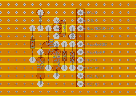
| jumunius wrote: | | Seems ok but things are a little tight in places. For example, there are a lot of trace cuts around the transistor. You might move everything to the right of the transistor over by a column or two, just to make sure you have room for soldering. Stripboard can be a little messier, easier to make solder bridges in my limited experience. Also, why not line up your wiring into columns -- you could more easily use headers to easily connect/disconnect in this case. |
You're absolutely right, Jumunius... I should have thought of those things in the first place. I moved some things around on the stripboard, taking advantage of the several unpopulated strips, and wound up with a layout that required only a single strip interruption (under the transistor, which now has a little more space, as you can see). I've actually become quite adept at soldering stripboard and have pretty much eliminated the problem of solder bridges. When I'm done with one I usually clean the strip side with alcohol (I use no clean solder, but the flux still leaves a slight residue that can be easy to mistake for a solder bridge if the light hits it just right) then I take a good look at it with a stereo microscope to verify all the solder joints... takes a little more time but eliminates headaches down the road.
| jumunius wrote: | | Yeah, that might be a hassle, I would recommend doing this in a way that is easier to detach. You want to be able to easily test and tweak as necessary. Plus, if you are still working on your C and D sections, you want to be able to work with the main board easily, without anything in the way. What if you decide to mod C and D? Things could get messy fast. And if you are relying on the wiring itself to hold your daughterboard in place, that sounds like a long-term stability problem, although the db will at least be light. |
Right again... This is why I asked for suggestions. As you can see from the updated pictures I've installed a header for the connection to the main board. The one missing terminal polarizes it so it can't be connected backwards... I should have done this in the first place.
| jumunius wrote: | | It sounds like part of the problem is you don't have an easy place to physically mount your daughterboard. It's hard to troubleshoot that without knowing what your enclosure looks like. I generally use mounting brackets made out of cheap sheet metal pieces from a hardware store, and they are big enough to attach a daughterboard off one end. Can take a pic later. |
That would be great... I really learn a lot from seeing other peoples' work. As for enclosure, I'm planning on keeping all my modular stuff in the same format... I got started in it with a dot-com entry system (only 3 installments left... yippeee  ) and have purchased a number of panels from Bridechamber in either dot.com or MOTM format for modules I'm building. The game plan for the Bass++ is to do a single panel for all 4 sections. I'll have plenty of room back there to mount this db, although I still think I'll look for a way to physically mount it to the main board. ) and have purchased a number of panels from Bridechamber in either dot.com or MOTM format for modules I'm building. The game plan for the Bass++ is to do a single panel for all 4 sections. I'll have plenty of room back there to mount this db, although I still think I'll look for a way to physically mount it to the main board.
| jumunius wrote: | Then to connect between boards, you should probably use the same sort of interconnects on your db that the Bass++ recommends for its panel wiring. That way you can disconnect everything from the main board to work on future sections.
As for the main board, you may be able to find sufficient room to drill 4 holes (on an edge?) and mount a header there, flying wires under the board to it. More likely, you just fly wires directly to your db interconnect and tie them off with wire wraps as best you can. As long as one section is disconnectable you will be happy. |
I have some breakaway 36-pin headers that I bought just for these kinds of situations... very handy and cheap to boot. I'm thinking I'll do all the wiring on the main board on the component side and then maybe just tie off the db to one of the other headers on that section... that may ultimately be the simplest approach. I'll know better once I've built the db and can wave it around the main board to see what will work best. I'm sure a reasonable solution will present itself... you know, one of those "light bulb" moments. 
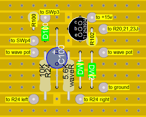
Anyway, here's the R2 layout.... thanks so much for the input, it is truly appreciated.
<marv>
(edit moments later.... I just noticed that I haven't grouped the connections on the header logically... some wires go to the main board, others to the panel. I think an R3 will be forthcoming that addresses this issue. It's a process, no? )
| Description: |
| Bass++ mods stripboard component side. |
|
| Filesize: |
91.95 KB |
| Viewed: |
65362 Time(s) |
|
| Description: |
| Bass++ mods stripboard bottom, looking through from component side. |
|
| Filesize: |
98.69 KB |
| Viewed: |
65363 Time(s) |
|
|
|
|
Back to top
|
|
|
jumunius
Joined: Apr 19, 2010
Posts: 346
Location: San Francisco, CA
Audio files: 13
|
| Posted: Sat Sep 10, 2011 9:21 am Post subject:
|
|
|
| Hey Marvkaye -- I haven't had a chance to give a serious look but in anticipation of V3, I should say -- you will need at least an extra column of space for your headers, 2 might be nice just to give yourself a little extra breathing room. Most headers I know of take up an extra column on either side. |
|
|
Back to top
|
|
|
marvkaye
Joined: Mar 14, 2011
Posts: 225
Location: Fla
|
|
|
Back to top
|
|
|
marvkaye
Joined: Mar 14, 2011
Posts: 225
Location: Fla
|
| Posted: Sun Sep 11, 2011 8:27 pm Post subject:
|
|
|
| What are the chances of someone coming up with a Bass++ mod to optimize one section for tuning the wave forms put out by the Blue Man Group pipe phone (for lack of a better name....).. you know, those contraptions made up from plumbing pipe that they play with foam spoon-shaped mallets? It's a really unique sound that I'd just love to have available. Any ideas out there? |
|
|
Back to top
|
|
|
jumunius
Joined: Apr 19, 2010
Posts: 346
Location: San Francisco, CA
Audio files: 13
|
| Posted: Mon Sep 12, 2011 10:02 am Post subject:
|
|
|
| marvkaye wrote: | | What are the chances of someone coming up with a Bass++ mod to optimize one section for tuning the wave forms put out by the Blue Man Group pipe phone (for lack of a better name....).. you know, those contraptions made up from plumbing pipe that they play with foam spoon-shaped mallets? It's a really unique sound that I'd just love to have available. Any ideas out there? |
Never seen them -- a link to a youtube video might help.
Like this? Although those sticks aren't spoon-shaped. |
|
|
Back to top
|
|
|
marvkaye
Joined: Mar 14, 2011
Posts: 225
Location: Fla
|
| Posted: Mon Sep 12, 2011 12:09 pm Post subject:
|
|
|
THis is one of their interesting instruments (the Drum Bone) but it's not the one I'm talking about... they play this one with sticks, AND there are snares in it. It also has a great sound, I wouldn't mind something setup for it as well. See it on youtube at http://youtu.be/aEWEHJuowLA (Corrected the link... first one put up was to a video by some yahoo that didn't include the original soundtrack. Found it at work on a soundless computer... last time I do that. )
The other instrument I was referring to is shown here. http://youtu.be/HRlm1wdhWp4.. I guess they call it the "Complex"... you'll see them playing it around one minute into the video. Then there's the portable version... http://youtu.be/W-yLfm5HsHc.
Cool stuff... seen them live a couple times, way excellent percussion entertainment.
<marv>
Last edited by marvkaye on Mon Sep 12, 2011 3:28 pm; edited 3 times in total |
|
|
Back to top
|
|
|
jumunius
Joined: Apr 19, 2010
Posts: 346
Location: San Francisco, CA
Audio files: 13
|
| Posted: Mon Sep 12, 2011 12:56 pm Post subject:
|
|
|
| marvkaye wrote: | | The other instrument I was referring to is shown here. http://youtu.be/HRlm1wdhWp4.. I guess they call it the "Complex"... you'll see them playing it around one minute into the video. |
Yeah, sounds cool -- almost like muted guitar. Wouldn't mind having one of those instruments.
As for doing that with a Bass++, I dunno. Firstly, the Bass++ isn't going to give you scaled tuning, so harmonies are out. Secondly, I think you'd need at least one filter controlled by an envelope to create those tones. You could add a simple filter and throw another decay/sweep combo onto it. But you might be better off routing the out of a Bass++ to a separate filter (or just leaving the Bass++ to normal drums and making the "Complex" a separate tunable synth). The much-sought-after Buchla 292 / LPG clone might be the best at recreating that sort of envelope response. (Just don't hold your breath if put in an order on the thread... you might as well write to Santa Claus.) |
|
|
Back to top
|
|
|
roglok

Joined: Aug 28, 2010
Posts: 202
Location: uptown
|
| Posted: Fri Oct 26, 2012 2:26 am Post subject:
|
|
|
I just finished a Bass++ using PickNick's single PCB layout. Almost works, but the VCA never shuts down completely - all controls work as expected, but the VCO is always on, even when no triggers are present.
Any suggestions where to start troubleshooting?
PS: I'm currently running this off 12V... |
|
|
Back to top
|
|
|
flab
Joined: Feb 13, 2012
Posts: 65
Location: Glasgow
|
| Posted: Wed Nov 21, 2012 7:36 am Post subject:
|
|
|
-roglok
im thinking of doing the same pcb running off 12V as well
any feedback from your 12V attempt ? |
|
|
Back to top
|
|
|
roglok
Joined: Aug 28, 2010
Posts: 202
Location: uptown
|
|
|
Back to top
|
|
|
flab
Joined: Feb 13, 2012
Posts: 65
Location: Glasgow
|
| Posted: Wed Nov 21, 2012 8:04 am Post subject:
|
|
|
good man
i shall use his pcb then and check the parts from the TH schem?
cheers |
|
|
Back to top
|
|
|
roglok
Joined: Aug 28, 2010
Posts: 202
Location: uptown
|
| Posted: Wed Nov 21, 2012 8:12 am Post subject:
|
|
|
| flab wrote: | good man
i shall use his pcb then and check the parts from the TH schem?
cheers |
yes. it was a bit of a pain to decipher the part numbers, but that's the way to go. picknick's design already includes the simple but cool diode waveshaper mod outlined here: http://electro-music.com/forum/topic-40457.html
i strongly suggest to clone the envelope and use one for pitch and the other for the VCA. instructions for this can also be found in the post linked above. the design gets a tiny bit more complex, but it's very rewarding. without separate pitch envelope i found the bass++ rather dull (as stated in the post over at muff's)
EDIT: erhm we ARE already in the "mods" post so just read the posts in this thread... |
|
|
Back to top
|
|
|
jeanpat
Joined: Jan 15, 2018
Posts: 7
Location: france
|
| Posted: Tue Apr 03, 2018 7:28 am Post subject:
|
|
|
hi guys!
I wat to build a bass++ as the peasant mod it, I'm wondering if I have some adaptation to do to implement back the cv input from the original design? That in the case I build powered by +9/-9v.
Otherwise could it be build as modded by the peasant and feed it with +12/-12v whitout any adaptations?
Sorry for my noobb's questions I'm not confident with all that powering adaptation.
Thanck you for your advices. |
|
|
Back to top
|
|
|
fallenmouse
Joined: Jan 31, 2022
Posts: 8
Location: Canada
|
| Posted: Tue Mar 01, 2022 8:57 am Post subject:
Wavefolder mod |
|
|
I've been playing around with a simple two-stage wavefolder addition/mod. It does require the addition of another IC (or bumping the dual opamp up to a quad, if you prefer, though that will likely raise hell with any layouts that have been worked out).
This adds some interesting, though maybe not super "natural"-sounding harmonics, giving a metalic shimmer to higher tones, and adding a bit of bite at the very low end of things, when used sparingly.
The 36k feedback resistor could probably be replaced with a far more common 39k, though this puts the output up around 30mVPP at the most extreme Fold settings, compared to the expected ~20mVPP.
My setup is running on 12V, but I can't see why this wouldn't work just fine with a 15V power supply.
https://tinyurl.com/ybpzyu9o |
|
|
Back to top
|
|
|
fallenmouse
Joined: Jan 31, 2022
Posts: 8
Location: Canada
|
| Posted: Sun Mar 06, 2022 5:47 pm Post subject:
Re: Wavefolder mod |
|
|
| fallenmouse wrote: | | I've been playing around with a simple two-stage wavefolder addition/mod. It does require the addition of another IC (or bumping the dual opamp up to a quad, if you prefer, though that will likely raise hell with any layouts that have been worked out). |
After some more messing around, I think I'm going to land on the following:
https://tinyurl.com/ybjk6kes
I've got the wavefolder right off the output of the oscilator OTA. The output of the wavefolder is around 20-25mVpp. It goes out through a small pot, which replaces the original shell volume pot that was on the other side of the VCA OTA. The new shell volume pot then goes into the input of an inverting mixer.
I've added a simple avalanche noise source, which gets boosted in the final opamp on a quad chip, and through its own small-value audio taper pot, and finally is mixed in with the shell volume, and sent straight off to the VCA OTA. I've opted to keep the matched 220r resistors to ground on the inputs, though, I'm not really sure if they're useful, or if they could just as easily be omited, and have the inverting input grounded. |
|
|
Back to top
|
|
|
fallenmouse
Joined: Jan 31, 2022
Posts: 8
Location: Canada
|
|
|
Back to top
|
|
|
|

 Forum index » DIY Hardware and Software » Thomas Henry designs