| Author |
Message |
Photon

Joined: Mar 22, 2005
Posts: 363
Location: Boston
Audio files: 1
|
|
|
Back to top
|
|
 |
TekniK

Joined: Aug 10, 2008
Posts: 1059
|
 Posted: Fri May 28, 2010 7:23 am Post subject: Posted: Fri May 28, 2010 7:23 am Post subject:
|
  |
|
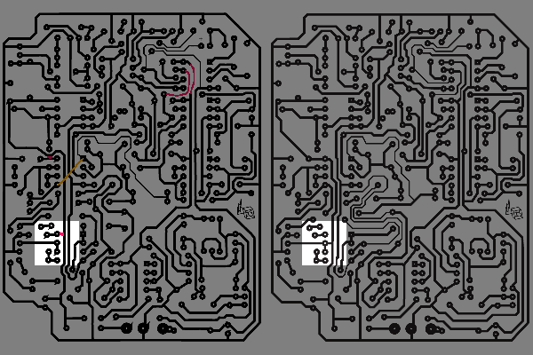
| Photon wrote: | | I haven't looked too close at this, but it looks like a different trace was connected rather than the one suggested. I'm not sure which is correct. |
It's that its not sure ,it's certain!
Am hours on circuits,and its sure its not good for the eyes.
many thanks,i fix i tright now.
EDIT: PDF IN FIRST POST IS UPDATED |
|
|
Back to top
|
|
|
ultrashock

Joined: Dec 10, 2009
Posts: 40
Location: Vienna.AT
|
| Posted: Wed Jun 30, 2010 6:13 am Post subject:
|
|
|
Dear guys!
Have you experimented with op-amps other than discounted CA3160?
Since the D. Bucha used 3160 in 259's Timbre, there were RC4136 (which are basically the uA741 in origin) in the Easel, and thus Lanterman supposed to substitute them by the "nearest" RC4558.
I made some Timbre model in ISIS Proteus. Nothing really special, just a Timbre-circuit with the scheme aforesaid and I tried LM358, TL072/074 and other ones ^_^ (unfortunately I did not managed to find the RC4558 or RC1558 spice models) and even so I observated some sine "shaping" into square wave with enriched harmonics in virtual oscilloscope (CPU activity was almost 100%  ). That is why I made the assumption for myself that it could be almost any op-amp (even better hi-fi OPA2137 or OPA4134), the difference could be only in the different sonic possibilities. ). That is why I made the assumption for myself that it could be almost any op-amp (even better hi-fi OPA2137 or OPA4134), the difference could be only in the different sonic possibilities.
What do you think about this?
p.s. : I also found some substitutes for J201: sst201, bf512, mmb4393.. yes, they are smd ones.
p.s. 2: thank you for the trick of having the 75K and 49K9 resistors, but I can not find those you told 72K and 43K in the circuit |
|
|
Back to top
|
|
|
janvanvolt

Joined: Nov 24, 2005
Posts: 285
Location: Mainz, Germany
|
|
|
Back to top
|
|
|
forbin
Joined: Jan 29, 2009
Posts: 120
Location: Fremantle, Australia
|
|
|
Back to top
|
|
|
janvanvolt
Joined: Nov 24, 2005
Posts: 285
Location: Mainz, Germany
|
| Posted: Thu Jul 01, 2010 9:27 am Post subject:
|
|
|
Just to be sure (again):
- left side of "fix.png" (previous posts) is the right one, so :
1) two RED connections to V+ on the left side,
2) orange wire
3) left wire on of the upper right, as the right wire already is going thru on my PCB.
please confirm shortly.
_________________
Homepage - http://www.czmok.de
My dIY - http://diy.czmok.de
Film/Music - http://gfm.me |
|
|
Back to top
|
|
|
forbin
Joined: Jan 29, 2009
Posts: 120
Location: Fremantle, Australia
|
| Posted: Thu Jul 01, 2010 4:57 pm Post subject:
|
|
|
Hi Janvanvolt
yes -- the red +V connections, the orange wire and the one left wire; i moved the existing upper-track a bit to show it could be done easily on the PCB... |
|
|
Back to top
|
|
|
mono-poly

Joined: Jul 07, 2004
Posts: 937
Location: Rotterdam, Netherlands
Audio files: 2
|
| Posted: Thu Jul 01, 2010 5:21 pm Post subject:
|
|
|
| I still think this is awesome |
|
|
Back to top
|
|
|
Dego

Joined: Apr 22, 2008
Posts: 139
Location: Sweden
|
|
|
Back to top
|
|
|
janvanvolt
Joined: Nov 24, 2005
Posts: 285
Location: Mainz, Germany
|
|
|
Back to top
|
|
|
forbin
Joined: Jan 29, 2009
Posts: 120
Location: Fremantle, Australia
|
| Posted: Wed Jul 14, 2010 12:32 am Post subject:
|
|
|
Xfade is crawling towards completion...
I have put in an LED and can certainly modulate it's brightness so the voltage control section seems good. Having said that the control range does seem pretty small. After about 1.7V the current limit protection circuit has kicked in -- this is equivalent to about 7mA through the LED in the vactrol. I have a suspicion that using a 1N4148 diode instead of a 1N457 may be the cause... Fixes are probably lowering the series resistor for the Vactrol LED; the data sheet suggests that the maximum current is 40mA and 7mA is well shy of that.... My Vactrol has turned up so I will try it as it certainly should be OK!
Will let you know how go tomorrow! |
|
|
Back to top
|
|
|
forbin
Joined: Jan 29, 2009
Posts: 120
Location: Fremantle, Australia
|
|
|
Back to top
|
|
|
janvanvolt
Joined: Nov 24, 2005
Posts: 285
Location: Mainz, Germany
|
| Posted: Tue Jul 20, 2010 3:50 pm Post subject:
|
|
|
I was using 1N4148 (and exchanged it now to 1N467) but i have issues with the XFADE. It does not seem to work at all ( or very quiet)
1)
Do i need to connect or use the Pre Gain/Post Gain Timbre Out ?
And what about XFADE.IN 1 Buffer out and XFADE.IN 2 Buffer out ?
(i did connect the Switch up/down)
2)
By watching Aarons Video ( http://il.youtube.com/watch?v=Pi3H1M555-M&feature=related) i saw that he swapped some PINs on the OPamps.
Is this fixed in the current design ?
_________________
Homepage - http://www.czmok.de
My dIY - http://diy.czmok.de
Film/Music - http://gfm.me |
|
|
Back to top
|
|
|
janvanvolt
Joined: Nov 24, 2005
Posts: 285
Location: Mainz, Germany
|
|
|
Back to top
|
|
|
TekniK
Joined: Aug 10, 2008
Posts: 1059
|
| Posted: Sun Jul 25, 2010 9:07 am Post subject:
|
|
|
| janvanvolt wrote: | | anybody able to help me troubleshooting ? |
For an answer on your second question in your previous post read post 1 of this topic. |
|
|
Back to top
|
|
|
janvanvolt
Joined: Nov 24, 2005
Posts: 285
Location: Mainz, Germany
|
| Posted: Sun Jul 25, 2010 9:52 am Post subject:
|
|
|
| TekniK wrote: | | For an answer on your second question in your previous post read post 1 of this topic. |
Thanks. Just wanted to be sure ...
Regarding the other question: I connected everything to the jacks + pots as described in the PDF, so i'd like to know if the PRE/POST in/out need to be connected in some way. if not - fine. I have issues that my Xfade does not work at all, so i'd like to ask for a bit of assistance to debug the issue.
_________________
Homepage - http://www.czmok.de
My dIY - http://diy.czmok.de
Film/Music - http://gfm.me |
|
|
Back to top
|
|
|
TekniK
Joined: Aug 10, 2008
Posts: 1059
|
| Posted: Sun Jul 25, 2010 10:14 am Post subject:
|
|
|
| I can't help you with that as i did not built the pcb yet,and i think am not gonna built the panner section anyway. |
|
|
Back to top
|
|
|
janvanvolt
Joined: Nov 24, 2005
Posts: 285
Location: Mainz, Germany
|
| Posted: Mon Jul 26, 2010 6:31 am Post subject:
|
|
|
| TekniK wrote: | | I can't help you with that as i did not built the pcb yet,and i think am not gonna built the panner section anyway. |
*sigh* thanks for letting me know
anybody else able to help me ?
_________________
Homepage - http://www.czmok.de
My dIY - http://diy.czmok.de
Film/Music - http://gfm.me |
|
|
Back to top
|
|
|
forbin
Joined: Jan 29, 2009
Posts: 120
Location: Fremantle, Australia
|
| Posted: Wed Jul 28, 2010 5:21 am Post subject:
|
|
|
Hi Janvanvolt
I will take another look at it in the morning and see if I can give you some more help... It does work but the scaling of the control and audio signals is a bit unusual for most modern synths. This part of the design was originally designed for providing a sort of morph between different waveforms from a VCO and that isn't really how it is being used here... I have sort of ended up using it just as a VCA (or gate to use Buchla parlance). |
|
|
Back to top
|
|
|
TekniK
Joined: Aug 10, 2008
Posts: 1059
|
|
|
Back to top
|
|
|
janvanvolt
Joined: Nov 24, 2005
Posts: 285
Location: Mainz, Germany
|
| Posted: Tue Nov 02, 2010 5:05 pm Post subject:
|
|
|
I am likely parting the module. Too much to hassle with. I have a dozen other open projects still pending and it does not bring me anything.
_________________
Homepage - http://www.czmok.de
My dIY - http://diy.czmok.de
Film/Music - http://gfm.me |
|
|
Back to top
|
|
|
vtl5c3
Joined: Sep 08, 2006
Posts: 425
Location: PDX
Audio files: 13
|
| Posted: Tue Nov 02, 2010 7:10 pm Post subject:
|
|
|
only a dozen?
| janvanvolt wrote: | | I am likely parting the module. Too much to hassle with. I have a dozen other open projects still pending and it does not bring me anything. |
|
|
|
Back to top
|
|
|
forbin
Joined: Jan 29, 2009
Posts: 120
Location: Fremantle, Australia
|
| Posted: Wed Nov 03, 2010 6:51 am Post subject:
|
|
|
| Hi Janvanvolt; sorry it has taken so long to reply! I think that the problem you are seeing is the perennial one with a lot of Buchla designs of that era in that the FET biasing of the Vgs is pretty critical. It tends to vary with FETs of the same type and even manufacturer. I had a lot of grief with the one in the waveshaper of the 258 VCO. It almost needs the gate to be driven with an op-amp with adjustable gain and offset to optimize the range of operation. All I can really suggest is experiment with other FET's and see... not very helpful really... |
|
|
Back to top
|
|
|
|

 Forum index » DIY Hardware and Software