| Author |
Message |
SebbeK
Joined: Apr 27, 2010
Posts: 7
Location: Sweden
|
|
|
Back to top
|
|
 |
adambee7
Joined: Apr 04, 2009
Posts: 420
Location: united kingdom
|
 Posted: Tue Apr 27, 2010 11:02 am Post subject: Posted: Tue Apr 27, 2010 11:02 am Post subject:
|
  |
|
Could you post the schematic so i can have a look please. Its probably something small and obvious. check all the right track cuts on the board, caps the right way round and such.  |
|
|
Back to top
|
|
|
SebbeK
Joined: Apr 27, 2010
Posts: 7
Location: Sweden
|
| Posted: Tue Apr 27, 2010 11:10 am Post subject:
|
|
|
Actually I don't have the scematics, I just followed the board layout.
I've tripple checked that. Also I just mesured the cuts to make sure that they don't make contact |
|
|
Back to top
|
|
|
mark_olson
Joined: Oct 26, 2006
Posts: 177
Location: Lawrence, Kansas
|
|
|
Back to top
|
|
|
SebbeK
Joined: Apr 27, 2010
Posts: 7
Location: Sweden
|
| Posted: Tue Apr 27, 2010 12:00 pm Post subject:
|
|
|
Yea, thanks. That's the one i'm using (the first one), i just checked it.
Any clue why it's not working? |
|
|
Back to top
|
|
|
adambee7
Joined: Apr 04, 2009
Posts: 420
Location: united kingdom
|
| Posted: Tue Apr 27, 2010 2:34 pm Post subject:
|
|
|
| i'll get around building it in the next couple of days. I've ordered the chip so i'll keep you informed. |
|
|
Back to top
|
|
|
Sebo

Joined: Apr 27, 2007
Posts: 564
Location: Argentina
|
| Posted: Tue Apr 27, 2010 4:01 pm Post subject:
|
|
|
Hi:
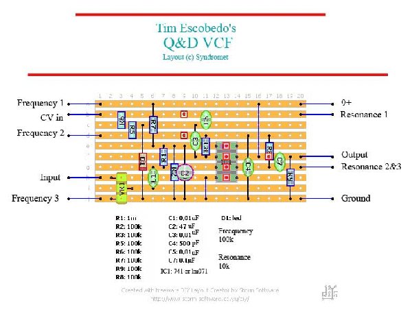
I built this circuit from the schematic and not from this stripboard layout,
but seeing the pic, I must note that there is a bridge to the left of the opamp
that connects the pin 4 of it to ground, that also connects the audio input to
ground (pin 4 and audio input shares the same strip). So I think you have
to cut that strip somewhere between VR1 and the opamp.
I didn't check all the layout, but that is something to start.
As a side note, when I built this circuit it sounds very strange, with no low end.
Some other guy that built this circuit to mod a Casio keyboard put a passive
low pass filter (RC) before the circuit, I did the same, but used a lower cutoff
frequency, and then the circuit start to sound like a VCF.
_________________
Sebo
---------------------------------------
My Music:
https://www.facebook.com/cosaquitos/ |
|
|
Back to top
|
|
|
SebbeK
Joined: Apr 27, 2010
Posts: 7
Location: Sweden
|
| Posted: Tue Apr 27, 2010 10:11 pm Post subject:
|
|
|
Thank you all 
Well spotted Sebo, I've now cutted the strip to the left of the jumper wire.
Now when no battery is connected and the audioinputs isn't grounded I get Very very low sound, but still no change with the pots. When a battery is connected no difference is made. When I ground the input jacks I get no sound.
If i ground the audio input like it was before, it gets amplified :S
Im using rca jacks for the input and output. The outer rings of the rca jacks is ground right? So i've connected them to eachother. When I say that I connect the jacks to the ground I simply put a wire between that wire that connects them to eachother, and ground on the circuit.
Also I suppose VR1 is a 1Mohm potentiometer or trim pot right? |
|
|
Back to top
|
|
|
globe town free arts lab

Joined: Nov 16, 2009
Posts: 12
Location: Globe Town
Audio files: 2
|
| Posted: Wed Apr 28, 2010 1:32 am Post subject:
|
|
|
In the schematic pin 1 of the IC is not connected.
But on the stripboard layout pin 1 is connected to r1, r2, r7 & c2.
try cutting the strip between pin 1 and c2
drew |
|
|
Back to top
|
|
|
SebbeK
Joined: Apr 27, 2010
Posts: 7
Location: Sweden
|
| Posted: Wed Apr 28, 2010 2:57 am Post subject:
|
|
|
Great, Thanks!
Now things are starting to happen. It oscillates!
With the rca jacks grounded it adds the ocillated tones to the music, and i can control the pitch with the 1Mohm pot and the frequency pot.
But this isn't exactly what I want   |
|
|
Back to top
|
|
|
SebbeK
Joined: Apr 27, 2010
Posts: 7
Location: Sweden
|
| Posted: Fri Apr 30, 2010 1:30 am Post subject:
|
|
|
maybe i should try to breadboard it....
Edit:
Breadborded! Still can't get it to work properly. Has anyone breadboarded the schematics? I'm doing the first one of the two versions.
It makes the sound quieter when the power is connected, and no sound at all without power.
I can disconnect the whole Vr section without any difference in sound. The cutoff and resonance pots don't do a thing. The trim pot affects the volume.
When I put the power on I can hear differences in the frequencies as some cap is charging up.
I have thripple checked it but I guess I've still done something wrong. Can someone please confirm that the schematics should work?
I have connected the circuit to a casio pt-10 keyboard this time. Cut the wire to the speaker and put it into the input of the circuit, and then the output is going to the speaker. Ground on the keyboard is tied to ground on the circuit (otherwise no sound is heard).
Edit2:
I had put the LED in the wrong way It's almost working now.
Two things though....
1. It chockes the sound Alot. The volume is very very low compared to the dry signal.
2. It Oscillates waay to easy.
I don't know the teory behind all this, I just now how the normal amplification works, not the "choose frequencies" part of it. So it's kinda hard for me to know how to fix it. Maybe I'll try the second version, without oscillations. However I don't have any .002 or .005uF caps... |
|
|
Back to top
|
|
|
SebbeK
Joined: Apr 27, 2010
Posts: 7
Location: Sweden
|
|
|
Back to top
|
|
|
|

 Forum index » DIY Hardware and Software