| Author |
Message |
elanhickler
Joined: Jun 24, 2008
Posts: 152
Location: Gilbert, Arizona
Audio files: 3
G2 patch files: 6
|
|
|
Back to top
|
|
 |
elmegil

Joined: Mar 20, 2012
Posts: 2179
Location: Chicago
Audio files: 16
|
 Posted: Sun Sep 09, 2012 11:39 am Post subject: Posted: Sun Sep 09, 2012 11:39 am Post subject:
|
  |
|
When the resistors are soldered in, they will be connected to other components that can and will give you readings different than the nominal value.
For the really basic example, if I have a 100k resistor that is mounted parallel to the CW and CCW legs of a 100k pot (this is not a real world example), if I try to measure it I will read 50k--because it's seeing the two 100k's in parallel.
There's not likely to be anything QUITE that simple in this circuit, but I have never been able to read resistance reliably once the circuit is soldered together. It *is* dependent on the details of the circuit, however.... |
|
|
Back to top
|
|
|
fonik

Joined: Jun 07, 2006
Posts: 3950
Location: Germany
Audio files: 23
|
| Posted: Sun Sep 09, 2012 1:15 pm Post subject:
|
|
|
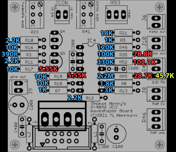
| Argitoth wrote: | What is going on? Look at what my multimeter gave me for resistor readings. I made doubly sure I was only touching the legs of the resistor. RED = multimeter shows wrong value. BLUE = BOM value. I re-tested R17 multiple times, even testing it from the bottom of the PCB. All resistor markings are correct, but the value isnt?!?!?!  |
like elmegil said, measuring resistors in circuit is not that simple, actually. it might be that there are resistances in parallel that you don't see at the first glance.
| Quote: | | What's more interesting? The PCB I have not wired (my other waveshaper) shows the correct values on my multimeter! |
wit ICs inserted? anyways, without wiring, and this wiring might cause parallel resistances...
_________________

cheers,
matthias
____________
Big Boss at fonitronik
Tech Buddy at Random*Source |
|
|
Back to top
|
|
|
elanhickler
Joined: Jun 24, 2008
Posts: 152
Location: Gilbert, Arizona
Audio files: 3
G2 patch files: 6
|
| Posted: Sun Sep 09, 2012 1:21 pm Post subject:
|
|
|
Yeah, I think my next step is to wire my other X-4046 VCO and put this one (the one we were debugging) through an oscilloscope to ensure the DC trimmers are correct. I do want to correct the weak sine signal. I'll have to debug that later. I know Dave Brown does debugging. Is there anyone else I might ask to look at my waveshaper if I can't figure it out?
Edit: As for the PWM init sensitivity, the square is now audible most of the turn, so that's good. Haven't tested PWM cv. |
|
|
Back to top
|
|
|
fonik
Joined: Jun 07, 2006
Posts: 3950
Location: Germany
Audio files: 23
|
| Posted: Wed Sep 12, 2012 12:14 pm Post subject:
|
|
|
BTW to all who are concerned/interested, i will order a few more PCBs end of month. so if you need some more, just tell me.
_________________
cheers,
matthias
____________
Big Boss at fonitronik
Tech Buddy at Random*Source |
|
|
Back to top
|
|
|
elanhickler
Joined: Jun 24, 2008
Posts: 152
Location: Gilbert, Arizona
Audio files: 3
G2 patch files: 6
|
| Posted: Thu Sep 13, 2012 3:15 pm Post subject:
|
|
|
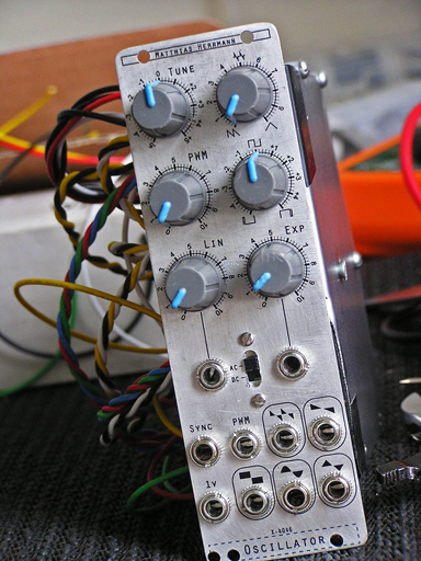
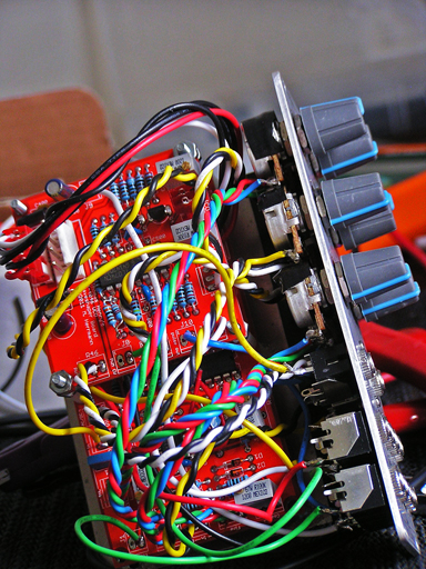
COMPLETED!!!! This is my second build, works flawlessly. Now I have this one to compare with my other one.
| Description: |
| FINALLY!! FINISHED!!! JEEZ!!! |
|
| Filesize: |
243.91 KB |
| Viewed: |
36895 Time(s) |
|
| Description: |
|
| Filesize: |
300.87 KB |
| Viewed: |
36896 Time(s) |
|
|
|
|
Back to top
|
|
|
elanhickler
Joined: Jun 24, 2008
Posts: 152
Location: Gilbert, Arizona
Audio files: 3
G2 patch files: 6
|
| Posted: Thu Sep 13, 2012 5:48 pm Post subject:
|
|
|
omg fonik!!!  the AC/DC switch is so weird! the AC/DC switch is so weird!
I'm using an SPDT on-on, Mouser #: 629-GS1150511
AC to top pin, DC to mid pin... wrong
DC to top pin, AC to mid pin... wrong again.
Turn the switch 180 degrees... correct!
wtf?   |
|
|
Back to top
|
|
|
HansRL
Joined: Nov 17, 2012
Posts: 15
Location: Norway
|
| Posted: Fri Nov 23, 2012 6:10 am Post subject:
PCB set wanted |
|
|
Hi.
Not sure if this is the popper way to indicate interest in the next batch, if there is going to be a new run of this PCB set?
Or if someone have an extra set they like to part with they can PM me?
Please excuse me if this is considered rude or improper behavior on this excellent forum.
thank you! |
|
|
Back to top
|
|
|
Mongo1
Joined: Aug 11, 2011
Posts: 411
Location: Raleigh NC
|
| Posted: Fri Nov 23, 2012 7:01 am Post subject:
|
|
|
| Quote: | AC to top pin, DC to mid pin... wrong
DC to top pin, AC to mid pin... wrong again.
Turn the switch 180 degrees... correct!
|
Electrically the first two options are the same. There can definitely be a bit of confusion though when wiring switches in general. The way to keep things straight is to envision the switch handle running through the body of the switch. It's a little like a teeter totter. When you push the handle down, the other end goes up and connects the top contact to the middle contact. When you raise the handle back up, the other end goes down, and connects the bottom to the middle contact.
Hope that helps
Gary |
|
|
Back to top
|
|
|
unterbit

Joined: Dec 08, 2008
Posts: 30
Location: Russia.St Petersburg
|
| Posted: Thu May 23, 2013 8:53 am Post subject:
|
|
|
Hello electro-music.com,Matthias & staff!
Little problem. I suppose i have built 4046vco with success,( i used SSM2210)but only issue i got is some ripple(not that firm spike at top of waveform) but more like "distortedlfo" interference.Funny that when i disconnected COARSE pot,issue has gone and signal appeared nice and clean..(with still connected FINE pot).Then i tried with another 100k COARSE pot & shot temp. wire but ripple came back. Ideas.. |
|
|
Back to top
|
|
|
elmegil
Joined: Mar 20, 2012
Posts: 2179
Location: Chicago
Audio files: 16
|
| Posted: Thu May 23, 2013 5:45 pm Post subject:
|
|
|
Shielded cable?
Like from TV cable, single conductor with a grounded (one end only) shield. |
|
|
Back to top
|
|
|
diablojoy

Joined: Sep 07, 2008
Posts: 809
Location: melbourne australia
Audio files: 11
|
| Posted: Thu May 23, 2013 9:17 pm Post subject:
|
|
|
check your power supply rails see if its got the same ripple on it.
might be coming from another module on the same supply
say an LFO or something with a led flashing at that rate,
if so maybe you are too close to the max current draw for your supply
or not enough decoupling on one of your modules
_________________
In an infinite universe one might very well
ask where the hell am I
oh yeah thats right the land of OZ
as good an answer as any |
|
|
Back to top
|
|
|
fonik
Joined: Jun 07, 2006
Posts: 3950
Location: Germany
Audio files: 23
|
| Posted: Thu May 23, 2013 10:52 pm Post subject:
|
|
|
yes.
and the fine pot is much less sensitive. maybe you just don't recognize the ripple.
BTW i once had a faulty potentiometer in the glide circuitry of my klee2. i replaced it, and the problem was still there. the replacement potentiometer has been faulty, too.
_________________
cheers,
matthias
____________
Big Boss at fonitronik
Tech Buddy at Random*Source |
|
|
Back to top
|
|
|
unterbit
Joined: Dec 08, 2008
Posts: 30
Location: Russia.St Petersburg
|
| Posted: Fri May 24, 2013 7:49 am Post subject:
|
|
|
How i could not mention that i have second VCO with the same deviance! and ripple kept in sync for both actually..So its PSU maybe,strangely but yesterday when i re switched the cab.everything was goodworking but today the ripple cameback.
Sorry Matthias for impeach X-4046 then! Need to go check the PSU.and thanks for all comments! |
|
|
Back to top
|
|
|
ortazel
Joined: Aug 30, 2013
Posts: 1
Location: US
|
| Posted: Fri Aug 30, 2013 4:36 pm Post subject:
|
|
|
I am pretty new to modulars and have done very little electronics DIY. I recently bought a secondhand X4046 VCO and the tuning is way off- 1V is more like a major 6th. I tried adjusting the HF and scale trim trimpots according to the documentation here: http://www.birthofasynth.com/Thomas_Henry/Pages/X-4046.html
but could only get it to about a 7th before the scale trimpot ran out- it sounds like it is close to getting to 1V/octave but not quite. I'm using a Minibrute with the arppegiator set on octaves to tune, which might not be ideal but should get me in the ball park at least- my Hertz Donut sounds great with it. What am I missing to calibrate this thing?
The sine out also sounds pretty far off what a perfect sine sounds like. I don't have an oscilloscope, is it even worth playing with the sine trimpots or should I just leave it alone and enjoy my weird sine?
I feel like I just need a slightly lower resistance trimpot for the scale so I can go that little bit further. The trimpots are all Bonems 3296, but all trimpots EXCEPT the scale trimpot have "W 104 / 110 T" printed on top. The scale trimpot has "W 101/ 302B" stamped on top. Should this be the case/is this the source of my problems? |
|
|
Back to top
|
|
|
fonik
Joined: Jun 07, 2006
Posts: 3950
Location: Germany
Audio files: 23
|
| Posted: Wed Sep 04, 2013 4:20 am Post subject:
|
|
|
so lets work it from the core forward.
to get a 1V/oct scale response you need to use the correct 4046. i.e. a texas instrument part would not do it. i used ON Semi and NXP with success. motorolla is good, too.
so what 4046 are you using?
_________________
cheers,
matthias
____________
Big Boss at fonitronik
Tech Buddy at Random*Source |
|
|
Back to top
|
|
|
Danno Gee Ray
Joined: Sep 25, 2005
Posts: 1351
Location: Telford, PA USA
|
| Posted: Thu Sep 05, 2013 9:54 am Post subject:
|
|
|
Matthias,
I would be interested in a PCB from your next run.
Do you by chance have panels available?
Dan |
|
|
Back to top
|
|
|
Moondog
Joined: Jul 19, 2013
Posts: 2
Location: Chcichester, UK
|
| Posted: Mon Sep 30, 2013 4:47 am Post subject:
|
|
|
Hi Matthias,
I too would like a couple of cores and a couple of wave shaper PCBs. Do let us know when you are doing a new run.
And thanks for all the hard work you are putting into the community, it gives great confidence to beginners like me to give it all a go.
Best,
Moon. |
|
|
Back to top
|
|
|
fonik
Joined: Jun 07, 2006
Posts: 3950
Location: Germany
Audio files: 23
|
| Posted: Mon Sep 30, 2013 8:42 am Post subject:
|
|
|
lately i got intrigued by the idea fo re-designing the PCB in order to facilitate eurorack builds w/o wiring. the same way i did it for the new thomas henry projects: one circuit PCB providing MTA-100 footprints, and an additional PCB for the front panel components, accommodating the eurorack standard.
quite some projects on the pile, so i don't know when this would happen.
_________________
cheers,
matthias
____________
Big Boss at fonitronik
Tech Buddy at Random*Source |
|
|
Back to top
|
|
|
Moondog
Joined: Jul 19, 2013
Posts: 2
Location: Chcichester, UK
|
| Posted: Mon Sep 30, 2013 9:11 am Post subject:
|
|
|
I can see the attraction, but it would preclude those of us with fat fingers wanting to build these projects to the larger standards.
Do you have any PCBs left? |
|
|
Back to top
|
|
|
fonik
Joined: Jun 07, 2006
Posts: 3950
Location: Germany
Audio files: 23
|
| Posted: Sat Oct 05, 2013 1:10 pm Post subject:
|
|
|
| Moondog wrote: | | I can see the attraction, but it would preclude those of us with fat fingers wanting to build these projects to the larger standards. |
actually not! in the past i did in a ways so that one could just buy and build the circuit PCB, which provides MTA-100 footprints for all controlls, doing manual wiring (so all standrads are possible).
and then there would be an additional PCB for the eurorack folks that would fit straight onto the mta-100 footprints for piggyback mounting...
| Quote: | | Do you have any PCBs left? |
unfortunately not.
i am currently doing two other project, nevertheless, one day i will re-order the x-4046. it is just that i don't want to run an online store and stock PCBs.
_________________
cheers,
matthias
____________
Big Boss at fonitronik
Tech Buddy at Random*Source |
|
|
Back to top
|
|
|
|

 Forum index » DIY Hardware and Software » fonik's place