| Author |
Message |
PHOBoS

Joined: Jan 14, 2010
Posts: 5947
Location: Moon Base
Audio files: 709
|
 Posted: Mon Aug 01, 2011 8:25 am Post subject:
VCO not working Posted: Mon Aug 01, 2011 8:25 am Post subject:
VCO not working |
  |
|
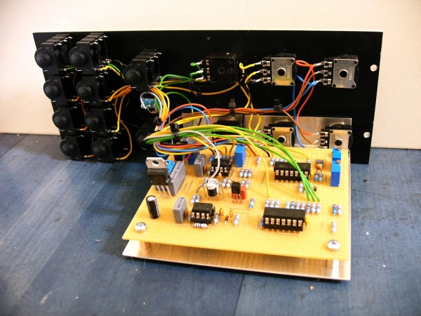
I 'finished' the VCO using 2 handmatched BC547B's and a TL072
I was hoping to get it tuned yesterday and play with it for a bit.
So as stated on the site I did the following;
| Quote: | 1. Before powering up, set all the trimmers to their mid-range position,
set the FREQUENCY pot to 5 (mid-range position), set the FINE TUNE pot to 0 (mid-range position),
set the LIN FM LEVEL, EXP FM LEVEL, PWM potentiometers to min (counter clockwise position),
and the PW potentiometer at 0 (mid-range position).
2. Connect the SAWTOOTH output to the oscilloscope (2V per square). Power-up the circuit. You should observe a sawtooth signal. |
well, I didn't see any signal (or almost any signal)
so I did some measurements and adjusted some of the pots a small bit to get the following readings:
trimpot T1: 0V (center)
trimpot T2: 10K [I have a 20K instead of a 25K and since it's not wired as a voltage divider
I just left it at about half the resistance]
trimpot T3: -5V (center)
trimpot T4: 7.5V (center)
Coarse tune pot: 0V (center)
Fine Tune pot: 0V (center)
PW pot: 0V (center)
Exp FM Level pot: 0V (CCW)
Lin FM Level pot: 0V (CCW)
PWM Level pot: 0V (CCW)
output U3a (pin1): 0V
output U3b (pin7): -0.6V
If I understand the circuit correctly everything after the output of U6a (pin1)
is just waveshaping and I should get a ramp signal at the ouput of U6a. So I
decided to do some more measurements at that point.
Using my oscilloscope to 'zoom in' on what didn't really seem to be anything
I found out that it's actually a traingle/sine wave with a amplitude of 2.4mVtt
and a frequency of 1.25MHZ  (I checked a couple of time to be sure) (I checked a couple of time to be sure)
I don't get 5V on the output of U7a (pin1) instead I get 4.5V. but if my math is correct
it can't be 5V because Vcc is lower than 15V. Anyway I measured the output voltages of the
2 voltage regulators and got +13.5 for the 78L15 and -14.3 for the 79L15. I tried several
78L15's and also a 7815 but got pretty much the same ouput voltage on all of them.
(without the ouput connected) I'm using a 49K9 resistor instead of 50K and I'm thinking of
using a resistor+trimpot for the 100K to adjust the ouput to be 5V.
now when I turn the coarse pot further CCW nothing happens but when I turn it CW a ramp signals
appears. Which got me the following readings:
Coarse tune pot: 5V
output U3a (pin1): -0.76V
output U6a (pin1): ramp, 53KHz, 4.2Vtt
Coarse tune pot: 10V
output U3a (pin1): -1.55V
output U6a (pin1): ramp, 104KHz, 7Vtt
Coarse tune pot: 14.85V (CW)
output U3a (pin1): -2.3V
output U6a (pin1): ramp, 227KHz, 9Vtt
so it does something but not what it should. also I don't seem to get a signal on the sineout
and the triangle out looks like a distorted sine with a very small amplitude. the pulse looks like
a trapezoid, the pulsewidth adjustment seems to be working though.
But I wanna focus on the section before the waveshaping for now.
I'm not using the PCB layout from the site but designed my own and build it on perfboard. I've checked
it over and over and over and I can't locate any flaws (which doesn't mean there aren't any). The solder
connection all seem to be correct but I'll check it again and again. I'm using a 2n3819 FET instead
of a J112 and replaced it after I found out I had it put in the wrong way around (apparently the pin
layout depends on the manufacturer). I also replaced the TL072 and LM311. but all of that didn't change
anything. So I'm stuck right now and would really like to get this module working.
Maybe someone can figure out what's wrong from the measurements or has some other ideas to test. 
| Description: |
|
| Filesize: |
845.87 KB |
| Viewed: |
565 Time(s) |
| This image has been reduced to fit the page. Click on it to enlarge. |
|
_________________
"My perf, it's full of holes!"
http://phobos.000space.com/
SoundCloud BandCamp MixCloud Stickney Synthyards Captain Collider Twitch YouTube |
|
|
Back to top
|
|
 |
yusynth

Joined: Nov 24, 2005
Posts: 1314
Location: France
|
| Posted: Mon Aug 01, 2011 9:26 am Post subject:
|
|
|
Since your circuit is on perfboard it is very difficult to give you clues cause it could be something with the routing of the pefboard.
Concerning some points in your description : 2N3819 is a NO NO for this circuit, a J112 provides the right performance. The 4.5V on the output of U7a (pin1) is OK since you have'nt 15V after the regulator (Read the note on my site and you'll see that the values you get after the regulator are what is to be expected).
The causes for your circuit not oscillating can be (in no particular order) a faulty J112, a faulty BC557B pair, a missing connection (for example the tempco not connected on one side).
What you can do is measuring the voltage at the output of U3a (pin 1) and check that when tweaking the Frequency knob, you observe a variation of the voltage at pin1 and on the basis of the first BC557B.
_________________
Yves |
|
|
Back to top
|
|
|
PHOBoS
Joined: Jan 14, 2010
Posts: 5947
Location: Moon Base
Audio files: 709
|
| Posted: Mon Aug 01, 2011 3:24 pm Post subject:
|
|
|
thanks for the fast responce, and for making all these nice circuits available 
I had read the part about the voltage drop on the regulators just thought
the positive one was a bit too low. (and I hope you mean BC547B pair )
Anyway after going over the board with my DVM I discovered that I had
forgotten to solder one side of C10. I didn't really expect it would make a
lot of difference but boy was I wrong. After powering it up a beautifull
ramp signal appeared on my scope (output U6a). and I can adjust it over
the full range  so I tried the saw output: perfect! triangle and sine so I tried the saw output: perfect! triangle and sine
looked good too allthough not completely right but that's what the tuning was for.
one thing did confuse me about that process though:
4. Connect the SINEWAVE output to the oscilloscope (2V per square).
Adjust the T4 trimmer to refine the sinewave shape. Then adjust
the T4 trimmer in order to balance the sinewave around the 0V
level. The triangle should ramp down from +4V to -4V. If necessary refine
the setting of T3 .
I have a nice saw, triangle and sine signal now. the pulse doesn't
seem to look right yet, and I also get an amplitude drop at higher
frequencies. But I still have to calibrate the V/OCT tracking. so that might
change something. but that'll have to wait till tomorrow,..
_________________
"My perf, it's full of holes!"
http://phobos.000space.com/
SoundCloud BandCamp MixCloud Stickney Synthyards Captain Collider Twitch YouTube |
|
|
Back to top
|
|
|
yusynth
Joined: Nov 24, 2005
Posts: 1314
Location: France
|
| Posted: Tue Aug 02, 2011 12:11 am Post subject:
|
|
|
OK that was C10 not soldered on one side. Yes C10 is very important it is there to avoid that the comparator LM311 enter ino auto-oscillation at ultrasonic frequencies (the 1.25 MHz you observed) which drive the FET (J112) at ultrasonic rate too and prohibits the normal oscillation of the VCO.
Concerning the voltage drop you observe at high frequency, on the sawtooth it should not occur before 10kHz and sould not exceed 20% (which makes it not audible). If you note a severe drop of voltage on the sine wave you may reduce the value of C12 down to 22p or 10p .
And for the sine trimming you are right, the second T4 should be a T3. I'll correct this on my page ASAP.
Regards
Yves
_________________
Yves |
|
|
Back to top
|
|
|
golemokafe
Joined: Oct 21, 2021
Posts: 3
Location: Macedonia
|
| Posted: Thu Oct 21, 2021 5:28 am Post subject:
|
|
|
Hi PHOBoS
Would you mind to share the perfboard layout for the VCO? |
|
|
Back to top
|
|
|
PHOBoS
Joined: Jan 14, 2010
Posts: 5947
Location: Moon Base
Audio files: 709
|
|
|
Back to top
|
|
|
golemokafe
Joined: Oct 21, 2021
Posts: 3
Location: Macedonia
|
| Posted: Sat Oct 23, 2021 1:31 am Post subject:
|
|
|
| Great, thanks! |
|
|
Back to top
|
|
|
PHOBoS
Joined: Jan 14, 2010
Posts: 5947
Location: Moon Base
Audio files: 709
|
| Posted: Sat Oct 23, 2021 6:42 am Post subject:
|
|
|
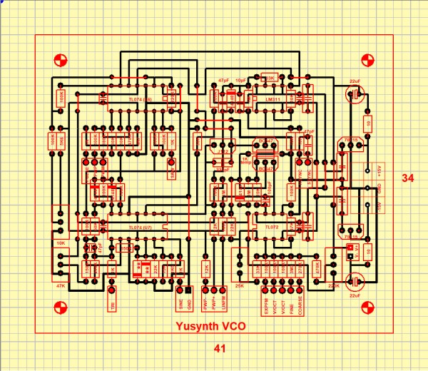
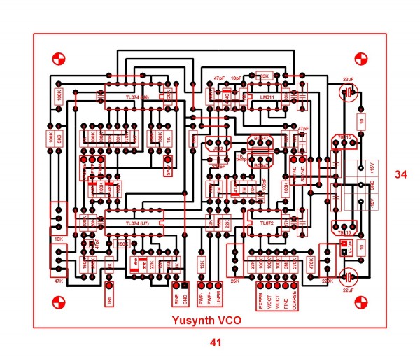
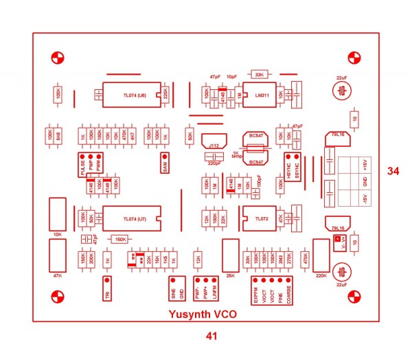
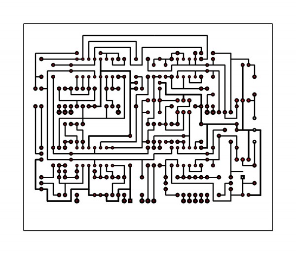
I hope these are useful.
The two diodes labeled with ** are matched 1N4148.
| Description: |
|
| Filesize: |
337.15 KB |
| Viewed: |
320 Time(s) |
| This image has been reduced to fit the page. Click on it to enlarge. |
|
| Description: |
|
| Filesize: |
206.97 KB |
| Viewed: |
355 Time(s) |
| This image has been reduced to fit the page. Click on it to enlarge. |
|
| Description: |
|
| Filesize: |
210.75 KB |
| Viewed: |
329 Time(s) |
| This image has been reduced to fit the page. Click on it to enlarge. |
|
_________________
"My perf, it's full of holes!"
http://phobos.000space.com/
SoundCloud BandCamp MixCloud Stickney Synthyards Captain Collider Twitch YouTube |
|
|
Back to top
|
|
|
golemokafe
Joined: Oct 21, 2021
Posts: 3
Location: Macedonia
|
| Posted: Sat Oct 23, 2021 11:30 pm Post subject:
|
|
|
| Thank you very much! |
|
|
Back to top
|
|
|
PHOBoS
Joined: Jan 14, 2010
Posts: 5947
Location: Moon Base
Audio files: 709
|
|
|
Back to top
|
|
|
|

 Forum index » DIY Hardware and Software » YuSynth