Posted: Thu Oct 06, 2011 2:57 am Post subject:
Single Op Amp SAW VCO Subject description: It actually works!!!
Hey folks!!!
I thought it's time to give something back to the community. Inspired by a thread from nicolas3141 - which can be found here: http://www.electro-music.com/forum/topic-38087.html - I wanted to build a very simple VCO. This is what I came up with.
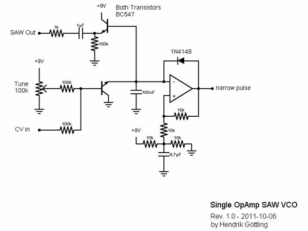
This little circuit uses one single Op Amp to generate a saw wave at the capacitor which is then buffered through a transistor. At the output of the op amp there is a very narrow pulse.
Frequency range is pretty huge and if my ears aren't wrong this thing has exponential pitch response. So with an expo converter it should be possible to get this thing to 1V/Oct. I haven't tried that yet.
This circuit works on a single supply - in this case on a 9V battery but it should work on almost any voltage. If you want to use a dual supply, simply exchange the lower voltage divider with a connection to ground.
The op amp is 1/2 of a TL062 but almost any op amp should work.
I'm currently working on a simple single op amp LFO for this little thing.
I'll post it as soon as it's finished. Also I'm thinking about a Saw to Tri converter to get some more waveforms from this circuit.
Oh, by the way - the output of the SAW is roughly 1/2 V-supply.
Have fun experimenting!!! Tell me what you think!!!
Cheers
Hendrik
[EDIT] The cap on the inverting input should be 10nF - but 100nF will also work...
single_opamp_saw_vco.jpg
Description:
This is the schematic of the ultra simple single op amp saw vco
Filesize:
18.2 KB
Viewed:
96422 Time(s)
_________________ "I don't care much about music. What I like is sounds." Last edited by metal_head_82 on Thu Oct 13, 2011 1:48 am; edited 1 time in total
the Diode sets the charge time of the cap to zero and therefore generating the sawtooth.
The discharge time of the cap is then determined by by Rce of the transistor which changes with the voltage present at its base.
You could exchange the CV-input section including the transistor with a pot connected to ground. Altering the pot would have the same effect on the pitch.
Basically this in an op amp version of a schmitt trigger oscillator.
Hope this helped a little...
Cheers,
Hendrik _________________ "I don't care much about music. What I like is sounds."
Joined: Nov 08, 2011 Posts: 2 Location: washington
Posted: Tue Nov 08, 2011 3:10 pm Post subject:
this is great. i'm a big fan forgoing stability for the sake of simplicity in module designes. i'd love to see a saw to tri converter for this, as well as an LFO. have you had any luck patching a few of these together with one in the lfo range? also, something i've been scouring the web for with little success is a simple VCO with only discrete transistors (no op amps). maybe you could lend a hand in designing something like this?
Joined: Aug 11, 2011 Posts: 411 Location: Raleigh NC
Posted: Tue Nov 08, 2011 3:44 pm Post subject:
Quote:
also, something i've been scouring the web for with little success is a simple VCO with only discrete transistors (no op amps). maybe you could lend a hand in designing something like this?
That shouldn't be all that hard to do. There are tons of transistor oscillators in existence. If you replace the 'R' that controls the frequency with an FET or perhaps a vactrol, you should be able to do it. But what do you gain by doing that? Opamps are pretty darned handy.
One other thought - look for schematics for vintage Korg synths. They used to use a lot of transistors in their designs. You might find something useful there.
Joined: Oct 20, 2008 Posts: 13 Location: Portland, Oregon
Posted: Thu Nov 10, 2011 6:58 am Post subject:
Opamps are great, but for me, discrete circuits might be easier to understand at a fundamental level. Nice circuit, maybe I will build it when I have a chance!
Joined: Sep 24, 2008 Posts: 25 Location: Chicago, IL USA
Posted: Tue Dec 20, 2011 7:13 pm Post subject:
Mongo1 wrote:
One other thought - look for schematics for vintage Korg synths. They used to use a lot of transistors in their designs. You might find something useful there.
Gary
Korg liked using a thyristor VCO circuit. I used a modified version of their VCO for the 2nd VCO bank for my Polysix. I added sync I/O, detune, etc. This was in 1996, so I'd have to find the documents on an old hard disk image.
Hey. Is it me, or shouldn't the CV transistor have emitter and collector swapped ? Or does this resistance thing work also with collector at a lower voltage than emitter ? Just asking, I'm pretty ignorant.
(ok I should just try it myself) _________________ ::U::N::S::C::H::N::E::L::L::
Yes, it can!
BUT you are using it as some sort of FM.
If you want hardsync you should connect the pulse-out of the first vco via a diode and a switch to the diode at the opamp's output of the second VCO.
(Hope this is clear enough - else I'll try to put a schematic online)
I've done this in the vco I'm currently working on. It's based on this design and has FM and hardsync. It's working pretty well BUT the expo converter gives me a headache.
Hope I could help you.
Cheers _________________ "I don't care much about music. What I like is sounds."
Yep. I forgot the diode ! And a switch ! Oh well I was nearly at it. But with the switch put as you explain, wouldn't osc#2 just reflect osc#1's frequency ? Hardsync as I understand it would be letting osc#2 live its own frequency life AND discharge its capacitor at osc#1's frequency… Anyway it was simply an idea I had while seeing your design, I'm not trying it yet. The whole thing would make quite a compact double VCO though !
Good luck in your researches ! _________________ ::U::N::S::C::H::N::E::L::L::
Sync - in this case hardsync - means that one osc restarts the cycle of another osc everytime its own cycle restarts. In this case that means that you need to set the output to high level and let the cap discharge - thus forming a saw.
But you could also discharge the cap. But the way you did it you simply set the CV with every pulse to the highest possible value => FM
But this sort of FM could sound very interesting - I would like to hear a sample of that
Keep up that great work and - in the words of Ray Wilson - stay ingenious! _________________ "I don't care much about music. What I like is sounds."
Ok thanks. My naive idea was to have the pulse to suddenly lower the transistor's resistance, thus discharging the cap enough to allow the comparator to restart a cycle. Fairly complicated indeed. And doesn't work, then…
While searching the forums for a nice and simple expo converter, I stumbled across a thread by synthmonger. He basically did the same thing as I did BUT he used a 40106 ic... It's the same thing but he uses schmitt triggers and I use an op amp as schmitt trigger... funny thing...
Joined: Feb 17, 2011 Posts: 79 Location: austria
Audio files: 2
Posted: Sun Feb 26, 2012 9:07 am Post subject:
hey hendrik,
thanks for the simple circuit. I didtn build it yet because I am more interested in a single supply lfo that outputs triangle, ramp or sawtooth.
But isnt it possible to use your circuit as a lfo? I mean is there a way to get a lower range out?
This would be double sick - cause then you would already have a VC-controlled LFO.
You could raise the cap value to a higher value, e.g. 1uF. This should work as well. But you have to keep in mind that the output of this circuit has DC offset. So instead of using a transistor for buffering you should use an opamp to add some gain and remove the offset.
I'll have to update my initial post as some values aren't correct. But basically this will also work as LFO with saw output. With a total of 3 opamps you could get saw and square/pulse.
I'll add the "advanced" version as soon as I have the time AND the schemaics finished. _________________ "I don't care much about music. What I like is sounds."
hi,
pretty new to electronics and still a freshman on this board...
I recently built -on breadboard so far - the version also referred to in this thread, around the 40106. then I got curious and also tried this circuit using 1/4 LM324. it differs from the schematic that I used 2n3904s (to have the same as in the 40106 circuit) and instead of the 100nf cap, which I tried, I went with a 470nF which gave me a more satisfying frequency range.
as i had them both sitting readily before me I thought it might be a good idea, and maybe of interest to some others here, to do an A/B comparison recording:
from breadboard into the soundcard. mono, no editing or anything, except cutting the respective parts into single files... I did a sweep over the full range a 100k pot gave me (and some little extra turns towards the end on most files.)
Joined: Jun 25, 2012 Posts: 20 Location: New England
Posted: Wed Mar 13, 2013 3:35 pm Post subject:
I know it's been a while since the last post but...
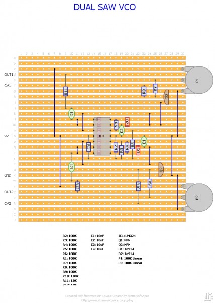
I made a somewhat crude stripboard layout for a dual version of this using an LM324. I took out the transistor buffer and replaced it with an op amp voltage follower using the spare op-amps in the LM324. All resistors are 100K except R11 and R12.
Note that I forgot to add the bypass cap across the bias voltage, but that's and easy fix.
Has anybody worked out a way to get it to do 1V/Oct yet?
EDIT: I finished building it using my layout today and can confirm it works!
Dual Saw VCO strip.jpg
Description:
Filesize:
397.93 KB
Viewed:
2086 Time(s)
This image has been reduced to fit the page. Click on it to enlarge.
man, that's the most satisfying piece of circuit, I ever found.
A sawtooth vco for ~ 1€ and it worked fine on breadboard.
Just wanted to tell that you really made me happy THANK YOU!
I'm pretty new to electronics, built my first 40106 schmitt trigger multivibrator in november 2012 :DDD
So if I feed the sawtooth output into the inverting input of an opamp and
e.g. a triangle lfo voltage into the non-inverting input, I get a pwm square/pulse wave? Is it really that easy?
In principle yes.
It's a basic Comparator.
The output is high as long as the level of the saw is above the threshold (the level of your modulation signal). If you change the threshold voltage you change the pulsewidth.
I hope I explained it right. You should check out the following site:
This is a very cool realtime circuit simulator with scopes. So you can check if your ideas work. But beware - it uses idealized components...
But definately worth a try to evaluate your ideas (the schematic obove is made from a screenshot of that simulator ) _________________ "I don't care much about music. What I like is sounds."
Tried with lm324 and tl074 and got the problem, that it always behaves strange. sometimes it doesn't work, sometimes the pulse width is different at 0v control input...
I still didn't buffer the vco out with an op amp, could this be the reason?
or is it about the stray capacitance of my breadboard? _________________ Is the future obsolete?
Joined: Mar 01, 2015 Posts: 24 Location: Alto, Michigan
Posted: Wed Mar 04, 2015 3:06 pm Post subject:
THIS IS AMAZING! Subject description: I know this is an old thread, but...
This is freaking amazing.
I just started trying to make my own electronic instruments, and this is one of the first things I've built that worked– on the first try!
It sounds AWESOME. Thank you SO MUCH for posting this. I can't say I understand what's going on in the circuit (I'm a total greenhorn) but this is the circuit I've been looking for.
So. Great. _________________ making stuff that makes sounds is awesome!
Posted: Fri Apr 17, 2015 5:16 am Post subject:
Exponential CV input
Hi all,
It's an old topic, but I thought I could add something anyway. I played around with this circuit, and I like it very much for its simplicity. Thank you for posting it! I have a few comments, and then I show the circuit how I built it so far.
1. Dual supply opamp: It's actually not so easy to use a dual supply opamp, and probably its not worth the trouble. To use dual supply, the transistor and the CV input should be referenced to the negative supply in stead of ground (the oscillation will be between +V/2 and -V/2, so you have to discharge to something more negative).
2. Linear vs exponential CV. The circuit can do both, or something in between! In the original post, it was mostly linear for audio frequencies. The reason is, that the transistor was used as a current amplilfier. The 100k transistor in the CV input path converts the CV to a current, and the transistor multiplies it by it's beta.
The alternative is to use the transistor as a voltage driven device. If you supply a voltage Vbe at the base (w.r.t. the emitter, which is ground), the transistor will allow an exponential Is current to flow into the collector,
Ic = Is exp(Vbe/Vth)
where Is is a device parameter and Vth is the 'thermal voltage', 25mV at room temperature. It is quite sensitive though, Vbe should be very close to the threshold (0.7V or so), and especially it is very temperature sensitive (hence the name thermal voltage).
I built it up as follows with roughly exponential CV. R9, R10 and R11 form a voltage divider with R5+R6 to set Vbe. R6 adjusts the scaling, and you can get roughly 1V/octave with a bit of twiddling around. R7 sets the lower frequency, so you can tune it roughly to the audio range, and then R8 gives good frequency adjustment range.
The CV tracking is not perfect, you always have some error either at higher or at lower octaves, but for 2-3 octaves this is reasonable. I think at high frequencies it still operates a bit in current-controlled regime, so probably one can improve for example by buffering the CV voltage.
OpampVCO.png
Description:
Version with approximately 1V/octave CV input
Filesize:
47.08 KB
Viewed:
2403 Time(s)
This image has been reduced to fit the page. Click on it to enlarge.
You cannot post new topics in this forum You cannot reply to topics in this forum You cannot edit your posts in this forum You cannot delete your posts in this forum You cannot vote in polls in this forum You cannot attach files in this forum You can download files in this forum

 Forum index » DIY Hardware and Software » Developers' Corner