| Author |
Message |
elmegil

Joined: Mar 20, 2012
Posts: 2179
Location: Chicago
Audio files: 16
|
 Posted: Sat Jan 05, 2013 10:49 pm Post subject: Posted: Sat Jan 05, 2013 10:49 pm Post subject:
|
  |
|
curiouser and curiouser....
Through this process, I found that my "and" logic for the trigger seemed to be sending two triggers on each note gate. In other words, if I turn off all but one of the switches, I'd get two triggers, one at the step with the switch on, and one at the next step.
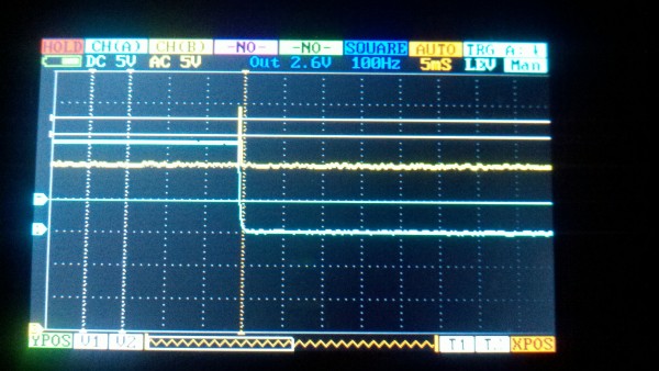
I figured that the AND of the clock and the gate were overlapping at the end as well as the start.... but when I looked at the trigger out on my scope, there was no actual trigger pulse that I could see on the trailing edge.
Then as I started turning the scope (a pocket DSO Quad) on and off, that also would effect the running. Sometimes turning it off would kill the trigger entirely. Later, it would simply cause the pulse to get stuck and no amount of banging around would make it go again until I turned the scope back on.
There are a LOT of connections here, I am not looking forward to yanking all the bus wire and redoing it.  But I don't think I see any other likely culprit (though why banging works....do cold solders work that way?).... But I don't think I see any other likely culprit (though why banging works....do cold solders work that way?).... |
|
|
Back to top
|
|
 |
ElektroBear
Joined: Feb 07, 2013
Posts: 11
Location: Sweden
|
| Posted: Tue Feb 12, 2013 4:42 pm Post subject:
|
|
|
Ive done a pcb that's basicaly a breakout for the pins on the 4017 mostly to get the connections in order to make it easier to troubleshoot when panelmounting so i'll give a writeup omorrow how my stripboard goes and after that i'll se about posting my pcb if thats of interest.
| elmegil wrote: |
.... (though why banging works....do cold solders work that way?).... |
yes they can, try and just rehating all the solderjoint with more solder or just flux if you got it. |
|
|
Back to top
|
|
|
elmegil
Joined: Mar 20, 2012
Posts: 2179
Location: Chicago
Audio files: 16
|
| Posted: Tue Mar 05, 2013 9:31 pm Post subject:
|
|
|
Well, the bad news is, the nifty clear case I had built this in fell and cracked beyond repair (cheap $10 pencil box/makeup box by Vaultz).
The good news is, I took it out of the enclosure and spent some time with it and realized I'd skipped a very important connection--pin 13 was not grounded, and in fact was floating. Grounding it appears to have solved the basic problem of random hangs.
I still need to make sure the and/clock logic works and that I'm not getting double pulses, but it gives me hope  |
|
|
Back to top
|
|
|
elmegil
Joined: Mar 20, 2012
Posts: 2179
Location: Chicago
Audio files: 16
|
|
|
Back to top
|
|
|
bubzy

Joined: Oct 27, 2010
Posts: 594
Location: United Kingdom
Audio files: 64
|
| Posted: Wed Mar 06, 2013 1:32 am Post subject:
|
|
|
got a schematic of what you are trying to do?
i've implemented this a couple of times in sequencers, it could be something easily rectified.
_________________
_Richard_ |
|
|
Back to top
|
|
|
elmegil
Joined: Mar 20, 2012
Posts: 2179
Location: Chicago
Audio files: 16
|
| Posted: Wed Mar 06, 2013 5:50 am Post subject:
|
|
|
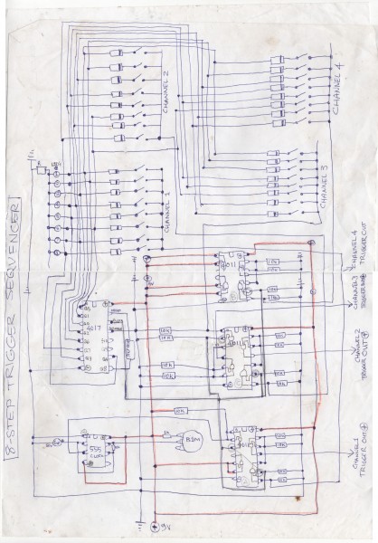
Didn't draw a schematic because it's a single AND gate.
clock from the 555 on the original stripboard, and gate from the standard arrangement of 4017 step -> switch -> diode -> common gate bus.
Each goes into one side for 4081 and gate and I take the trigger from there. |
|
|
Back to top
|
|
|
-minus-
Joined: Oct 26, 2008
Posts: 787
Audio files: 13
|
| Posted: Wed Mar 06, 2013 7:45 am Post subject:
|
|
|
| No sure if I fully understand what's going on, but to get a trigger in the past I have inverted the clock signal first to get a narrower pulse to clock the 4017, then AND it with the step output/gate from the 4017. I used a 4011 to do this if I remember. |
|
|
Back to top
|
|
|
elmegil
Joined: Mar 20, 2012
Posts: 2179
Location: Chicago
Audio files: 16
|
| Posted: Wed Mar 06, 2013 11:43 pm Post subject:
|
|
|
Actually I'm wrong, I did rewire this pretty significantly, I forgot that the 555 was doing a negative going pulse....
First schem is my current config, second is what I'm proposing, except I'm not sure what values to use.
| Description: |
|
| Filesize: |
9.42 KB |
| Viewed: |
1060 Time(s) |
| This image has been reduced to fit the page. Click on it to enlarge. |

|
| Description: |
|
| Filesize: |
10.16 KB |
| Viewed: |
952 Time(s) |
| This image has been reduced to fit the page. Click on it to enlarge. |

|
|
|
|
Back to top
|
|
|
PHOBoS

Joined: Jan 14, 2010
Posts: 5890
Location: Moon Base
Audio files: 709
|
|
|
Back to top
|
|
|
-minus-
Joined: Oct 26, 2008
Posts: 787
Audio files: 13
|
|
|
Back to top
|
|
|
elmegil
Joined: Mar 20, 2012
Posts: 2179
Location: Chicago
Audio files: 16
|
| Posted: Thu Mar 07, 2013 8:55 pm Post subject:
|
|
|
The only difference I can see in what you're doing vs what I'm doing is that you're using NAND gates, and I used a transistor inverter and an AND gate.
I *am* confused by all the 10k pull ups and pull downs on everything though |
|
|
Back to top
|
|
|
-minus-
Joined: Oct 26, 2008
Posts: 787
Audio files: 13
|
| Posted: Thu Mar 07, 2013 11:44 pm Post subject:
|
|
|
| elmegil wrote: |
I *am* confused by all the 10k pull ups and pull downs on everything though |
Well I'm equally confused by that  . So you are inverting your clock, sending that to the 4017 to clock it, and AND-ing the 4017 output with the inverted clock? Strange it isn't working. That sequencer I made certainly works. I still use it to test things as I haven't yet replaced it. . So you are inverting your clock, sending that to the 4017 to clock it, and AND-ing the 4017 output with the inverted clock? Strange it isn't working. That sequencer I made certainly works. I still use it to test things as I haven't yet replaced it.
It's very odd what you are experiencing. Not sure what to suggest. One of those Ken Stone Gate to Trigger circuits would perhaps clean this up would it? I've built a few of them and they work well...
Last edited by -minus- on Sat Mar 09, 2013 1:12 am; edited 1 time in total |
|
|
Back to top
|
|
|
elmegil
Joined: Mar 20, 2012
Posts: 2179
Location: Chicago
Audio files: 16
|
| Posted: Fri Mar 08, 2013 6:29 am Post subject:
|
|
|
If all my switches are on, it works great, now that I've properly grounded pin 13 of the 4017.
What's going wrong is that if I have a switch off, I still get a tiny trigger as the gate is dropping. More switches off in a row, and they all stay off, no triggers.
I can see on the scope trace exactly what's going on--It's the clock that causes the 4017 to advance to the next step, and the gate takes some time to drop, so the leading edge of the clock and trailing edge of the gate are both "high" for enough time that the AND gate sends out a high signal. It's under 1ms, but it's enough to trigger at least my soundlab which I've been using to test this.
The only thing I can think is that since you're going through 4 gates as opposed to me going through a single gate, somehow the gate delay is just long enough to prevent this, or the 4011 response times are different than the 4081. I have the clock and gate outputs going to jacks, so what I probably ought to do is throw a 4011 on a breadboard and see if it behaves the same when hooked up exactly like your circuit (well, except for the inversion of the clock, undoing the transistor will be harder than changing the rest of the logic).
Edit: one other possibly relevant difference is the supply voltage. You're at 9V and I'm at 15V for testing. A <1ms pulse from 9V may not be enough to trigger things that a 15V pulse is, esp considering the soundlab is a 9V device. It'll take (a tiny bit) longer for the 15V pulse to drop back off.... I can hook my 9V batteries back up to it though.... |
|
|
Back to top
|
|
|
-minus-
Joined: Oct 26, 2008
Posts: 787
Audio files: 13
|
| Posted: Fri Mar 08, 2013 7:07 am Post subject:
|
|
|
Well perhaps the fact I have run mine from 9V is the difference like you said. I'm not sure the NAND making AND or simply using an AND IC would be different.
After I read through your previous posts I saw that you were doing the same thing as me anyway.
Yeah, try it a 9V and see what that does. |
|
|
Back to top
|
|
|
elmegil
Joined: Mar 20, 2012
Posts: 2179
Location: Chicago
Audio files: 16
|
| Posted: Fri Mar 08, 2013 10:39 pm Post subject:
|
|
|
Facts observed:
9V doesn't matter.
4011 (two stages anyway, NAND + inversion) doesn't matter.
I've attempted to filter on the output side (not like the schem above) with a 1K resistor in series and a cap to ground, trying sizes from 100pF up to 10uF, doesn't matter. Subbed in a 10K, also doesn't matter.
Rawr. |
|
|
Back to top
|
|
|
-minus-
Joined: Oct 26, 2008
Posts: 787
Audio files: 13
|
| Posted: Fri Mar 08, 2013 10:49 pm Post subject:
|
|
|
Wow this is very strange.  Maybe the fact I didn't add the 100nF caps to the IC power pins on mine is making it 'work'? Maybe the fact I didn't add the 100nF caps to the IC power pins on mine is making it 'work'?
I really don't know what to suggest. I have not experienced double triggering like you have. I should hook mine up and do some tests and look at it on a scope which I have never done. |
|
|
Back to top
|
|
|
elmegil
Joined: Mar 20, 2012
Posts: 2179
Location: Chicago
Audio files: 16
|
| Posted: Fri Mar 08, 2013 11:15 pm Post subject:
|
|
|
The only thing I have left to think is maybe it's a high enough voltage it takes too long to drop (at 15V or 9V), and if I clamped it to 5V maybe it would behave better.
I'm just not getting it though, this is a really simple circuit, and I've gone over Fonik's Baby-10 schematic as well--there's not anything special I've seen any of them do to avoid this problem. |
|
|
Back to top
|
|
|
-minus-
Joined: Oct 26, 2008
Posts: 787
Audio files: 13
|
| Posted: Sat Mar 09, 2013 12:07 am Post subject:
|
|
|
I've just looked at Fonik's Baby 10. He is feeding his clock through a CGS Gate to Trigger converter then into his decade counter. He seems to be taking the gate output and sending that through the other Gate to Trigger circuit on the IC. What I don't get is how is he managing to trigger on consecutive steps from this. You'd need a gap of some sort between steps which the 4017 doesn't have. 
But look, maybe there is a possible solution in this. What about sending the clock from the 555 through a Ken Stone Gate to Trigger Converter then into the 4017? Would that clean up the clock or is this more to do with the gate from the 4017 taking a while to drop off?
EDIT: I'm just reading through this:
http://electro-music.com/forum/viewtopic.php?highlight=fonik+baby&t=36133
I guess you might have read this...
EDIT No. 2!
Actually, what about what PHOboS was saying earlier... If you clocked the 4017 with a non-inverted signal from the 555, then AND an inverted clock with the 4017 gate signals to obtain a trigger. Surely there would be a sufficient delay to eliminate this problem? ... although I think I'm suggesting the opposite of what PHOboS is saying .
I've got to get out the sequencer I made and see if I have this problem but somehow never noticed! |
|
|
Back to top
|
|
|
elmegil
Joined: Mar 20, 2012
Posts: 2179
Location: Chicago
Audio files: 16
|
| Posted: Sat Mar 09, 2013 8:07 am Post subject:
|
|
|
The clock seems plenty clean.
I'm trying to think what that inversion method would look like....
Ok, drew it out on graph paper. #1, that moves the trigger to the trailing edge of the gate rather than the leading edge. #2, it looks to me like I'd have the same problem at the leading edge instead.
This seems relevant:
| Quote: | | Fonik, I have built your version of the Baby10 and made some adaptations including this one. Unfortunately this wasn't as simple as you described it. You will have to take the propagation delay of the 4017 into account. If you don't do, the gate signal will occur later then the clock signal and will, due to lasting too long, also send out a trigger signal on the next step. To counter this you can chain some AND gates to add some delay to the clock signal. |
So when I tried this with the 4011, I inverted the output of the NAND, but still did the NAND at the first step. This sounds like I need to invert the clock twice and then NAND and invert again, or I need to run the clock through some of my AND gates (on the 4081) before ANDing with the gate.
There's also this:
| Quote: | | An incovenience with this version of the baby10 is that u can not obtain 2 trigger signals after each one.This is because if u activates 2 gates after each one the result will be one long gate signal.This can be resolved by adding an 4081 AND gate:by 'AND-ing' the clock with the output u get triggers that are the same lenght as the clock signal.The problem is that because of the propagation delay from the 4017 the gate signal will become a bit later then the clock signal.Because of this gate signal shift u will get another trigger at the next step even this will not be desired.To resolve this u can use the remaining EN gates of the 4081 to allign the clock with the gate signal (but this u should test it first as its not guaranteed that this will work) |
Which sounds like maybe I could run the gate into several of the AND gates, then put the clock into the first, the output of that set into the second, and so forth and maybe that would trim this bump as well.
Let me try these two approaches and see.
(BTW, clearly, I had not read that thread before, thank you for finding and referencing it  ) ) |
|
|
Back to top
|
|
|
elmegil
Joined: Mar 20, 2012
Posts: 2179
Location: Chicago
Audio files: 16
|
| Posted: Sat Mar 09, 2013 11:05 am Post subject:
|
|
|
Neither one of those approaches helped. I also tried using the gate delay of a 40106 hex schmitt inverter, and had 4 inverters in line with the clock side and that didn't help either.
So I turned to the idea that I need to debounce the output of the AND.
Using a fairly standard approach, 330K to .1uF cap, I get no trigger through at all. If I drop the resistor down to 100K or 120K it gives me double triggers. 150K gets no trigger. Putting resistors in series I narrowed it down to 130K still giving me a double trigger, but 135K none at all. I tried 131K and then weirdness ensued: the trailing trigger got through, but the main trigger did not.
I will have to hook this up to a scope later to see what the heck that's about. |
|
|
Back to top
|
|
|
-minus-
Joined: Oct 26, 2008
Posts: 787
Audio files: 13
|
| Posted: Sat Mar 09, 2013 11:57 am Post subject:
|
|
|
OK, so you tried clocking the 4017 with a NON inverted pulse from the 555, and then using an INVERTED 555 clock ANDed that with the 4017?
There must be a solution to this. Either sorting out the gate issue, or delaying the clock somehow.
What about flip flopping the clock? so you send the clock to a 4013 and take the one Q output to the 4017 to advance the steps, and the other Q (Q with a little bar over it ) you use to AND with the step. Would that give you a trigger point in the middle of the step? Might be too large a delay actually. Particularly if the clock is slow.
Yeah, I don't know. It's tricky isn't it? 
I'm thinking that with the sequencer I made, I haven't noticed this behaviour because I have only ever triggered those 808 modules with it which might not be as picky as the Soundlab.
Here's an article on debouncing. It sorted out some issues I was having with a non-synth related problem recently. Not sure if it would be of use but interesting all the same:
http://www.ganssle.com/debouncing-pt2.htm |
|
|
Back to top
|
|
|
-minus-
Joined: Oct 26, 2008
Posts: 787
Audio files: 13
|
| Posted: Sat Mar 09, 2013 12:13 pm Post subject:
|
|
|
Just thinking out loud and not sure if this will work....
What about sending the 555 pulse (inverted or non inverted) to a 4013 input. The Q out will be dividing the clock from the 555 by 2. Then take to Q out from the 4013 to the 4017. So it takes two clock pulses from the 555 to get the 4017 to advance a step.
The 4017 has your trigger switches at each step. So you AND the steps with the 4013. This gives a gate half the length of the 4017 gate/step length. Then you AND the output of this with the original 555 clock pulse to give the trigger.
I'm thinking this will eliminate the lagging 4017 gate at each step because you can shortened it by half. Do you thing this would work?
EDIT: Actually I don't think this will work because there would still be that lag from the 4017! It's about time someone makes a decade counter with a trigger out. This logic does my head in! |
|
|
Back to top
|
|
|
elmegil
Joined: Mar 20, 2012
Posts: 2179
Location: Chicago
Audio files: 16
|
| Posted: Sat Mar 09, 2013 12:44 pm Post subject:
|
|
|
I wonder if the trigger conditioner might help this. the cap/diode circuit....
That'll be next, but we'll see when I get to it.
I didn't do the non-inverted version because it just inverts the problem Gives me spurious leading edge triggers, and it also makes the step trigger occur at the end of the cycle which would put it at the end of the gate for anything where I was doing alternating switches. |
|
|
Back to top
|
|
|
-minus-
Joined: Oct 26, 2008
Posts: 787
Audio files: 13
|
| Posted: Sat Mar 09, 2013 12:52 pm Post subject:
|
|
|
I'd try the Ken Stone Gate to Trigger circuit. They are excellent and very easy to build. I was so impressed I made six of them! This seems to be what Fonik is using.
I have PM'd Fonik out of desperation! Maybe he will have some advice. |
|
|
Back to top
|
|
|
elmegil
Joined: Mar 20, 2012
Posts: 2179
Location: Chicago
Audio files: 16
|
| Posted: Sat Mar 09, 2013 1:35 pm Post subject:
|
|
|
Yeah, the Ken Stone Circuit, as shown in the Baby 10 schematic, is what I had in mind.
No love.
I did figure out what was up with my first step: it was cranked all the way up so it was a frequency past my hearing. |
|
|
Back to top
|
|
|
|

 Forum index » DIY Hardware and Software » The layout factory