| Author |
Message |
Inventor
Stream Operator

Joined: Oct 13, 2007
Posts: 6221
Location: near Austin, Tx, USA
Audio files: 267
|
|
|
Back to top
|
|
 |
Inventor
Stream Operator
Joined: Oct 13, 2007
Posts: 6221
Location: near Austin, Tx, USA
Audio files: 267
|
|
|
Back to top
|
|
|
JingleJoe

Joined: Nov 10, 2011
Posts: 878
Location: Lancashire, England
Audio files: 14
|
 Posted: Sun Jun 24, 2012 12:25 am Post subject: Posted: Sun Jun 24, 2012 12:25 am Post subject:
|
  |
|
A good few posts back I would have suggested the 4089 or 4516 up/down counter for things with 4 bit input, 4516 has 4 bit preset input and a few other options which make it do interesting things 
I've never heard a chip which sounded more like digital patterns look than the 4089 
I did a thread about it a while ago, called something like "4070 experiments" because I was experimenting with making horrible noises with a XOR gate I used the 4089 to make a little sequencer with a changing pattern by using it to gate audio by putting the audio frequency square wave into the strobe input you can do a lot with that chip, but I don't know about true multiplication as it multiplies by a fraction, like 1/16, so you end up with division. If I overloked something and this thing can multiply by whole numbers, please enlighten me because that would be fantastic 
What you have there inventor looks brilliant! Nice and simple, just the way I like it Carry on the good work chaps!
_________________
As a mad scientist I am ruled by the dictum of science: "I could be wrong about this but lets find out"
Green Dungeon Alchemist Laboratories |
|
|
Back to top
|
|
|
Inventor
Stream Operator
Joined: Oct 13, 2007
Posts: 6221
Location: near Austin, Tx, USA
Audio files: 267
|
| Posted: Sun Jun 24, 2012 2:12 am Post subject:
|
|
|
Joe, the multiplication would occur if you hooked two CD4089 chips in series, or with a similar two-chip configuration you can get addition. Read the data sheet carefully and you'll find mention of this on page 1 and two schematics several pages later.
For our purposes, it is a multiplier in the sense that we do get a fraction which is (X/16)/Y, or X/(16*Y), where 1<=x<=16 and 2<=Y<=9. So our slowest frequency will be 1/(16*9)*fo, or 0.007*fo and our fastest frequency will be 16/(16*2), or 0.5*fo. I set F0 to be around 1 to 1.5 kHz, so our frequency range will be in the neighborhood of 10Hz to 600Hz which is really quite a wide range of frequencies. Or with a cap/resistor change we could get 20Hz to 1250 Hz, maybe that would be better.
I mean, you're right that it is always dividing or in other words always producing a lower frequency than the input, but we just crank up the input frequency to compensate for that. We get a numerator that ranges from 1 to 16 and a denominator that ranges from 2 to 9.
Les
_________________
"Let's make noise for peace." - Kijjaz |
|
|
Back to top
|
|
|
Inventor
Stream Operator
Joined: Oct 13, 2007
Posts: 6221
Location: near Austin, Tx, USA
Audio files: 267
|
| Posted: Sun Jun 24, 2012 2:19 am Post subject:
|
|
|
| JingleJoe wrote: | | What you have there inventor looks brilliant! Nice and simple, just the way I like it Carry on the good work chaps! |
Well I somehow managed to consume the better part of two 2-liter bottles of soda since yesterday around 1pm. It's 4am the next day now and I'm buzzing like a hummingbird, lol. Plus I slept like a baby for almost 24 hours prior to that so I'm rested. Therefore: huge design effort! I took photos too.
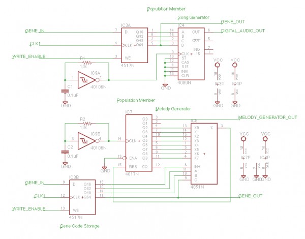
First: the results! Below are two images, the schematic and the pcb of the completed design. At this point the only thing that worries me is the debunking of the switches, but I believe they will operate properly without debunking, believe it or not! Maybe that's wishful thinking...
Les
| Description: |
| the schematic, ir's too small to read so I'll post detailed images later. This is just for an overview of how it's all connected. |
|
| Filesize: |
153.52 KB |
| Viewed: |
528 Time(s) |
| This image has been reduced to fit the page. Click on it to enlarge. |

|
| Description: |
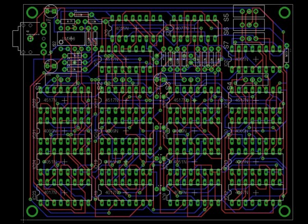
| The PCB. I can't believe it auto routed fully, wow that's nice! |
|
| Filesize: |
405.85 KB |
| Viewed: |
407 Time(s) |
| This image has been reduced to fit the page. Click on it to enlarge. |
|
_________________
"Let's make noise for peace." - Kijjaz |
|
|
Back to top
|
|
|
Inventor
Stream Operator
Joined: Oct 13, 2007
Posts: 6221
Location: near Austin, Tx, USA
Audio files: 267
|
| Posted: Sun Jun 24, 2012 2:28 am Post subject:
|
|
|
The population circuit (#3) was posted earlier so I won't repost it.
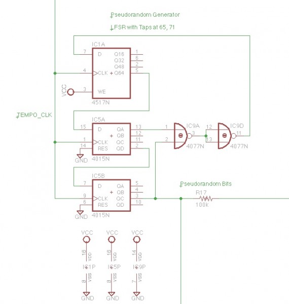
The LFSR circuit is shown below, it is a 71 stage shift register with taps at 71 and 65. It's only a three chip implementation, which is really only 2.5 chips because the other two XNOR gates are used for the two clock oscillators, shown below as well.
The oscillators are modeled after the Relaxation Oscillator that one normally uses an opamp or comparator to construct. If you think about how the relaxation oscillator works and how similar an XNOR gate is to an opamp or comparator, then you see how these oscillators work. We need one a tempo rate and another at audio rate.
Les
P.S. the resistor at the output of the LFSR is a little mixing trick that I will explain in the next post.
| Description: |
| The LFSR (is it Linear Feedback Shift Register or Logic Feedback Shift Register? I forget). |
|
| Filesize: |
64.43 KB |
| Viewed: |
400 Time(s) |
| This image has been reduced to fit the page. Click on it to enlarge. |
|
| Description: |
|
| Filesize: |
50.15 KB |
| Viewed: |
386 Time(s) |
| This image has been reduced to fit the page. Click on it to enlarge. |

|
_________________
"Let's make noise for peace." - Kijjaz |
|
|
Back to top
|
|
|
Inventor
Stream Operator
Joined: Oct 13, 2007
Posts: 6221
Location: near Austin, Tx, USA
Audio files: 267
|
|
|
Back to top
|
|
|
Uncle Krunkus
Moderator

Joined: Jul 11, 2005
Posts: 4761
Location: Sydney, Australia
Audio files: 52
G2 patch files: 1
|
| Posted: Sun Jun 24, 2012 5:50 am Post subject:
|
|
|
Some beautifull work there Les! 
It'll be a while before I get my head around though.  
_________________
What makes a space ours, is what we put there, and what we do there. |
|
|
Back to top
|
|
|
Inventor
Stream Operator
Joined: Oct 13, 2007
Posts: 6221
Location: near Austin, Tx, USA
Audio files: 267
|
| Posted: Sun Jun 24, 2012 9:06 am Post subject:
|
|
|
Thanks Uncle, it's going to be a good circuit to build and test.
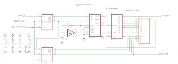
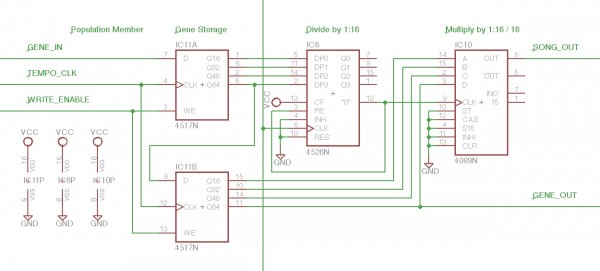
I added SRFF debunking on the write enable switches and fixed the reproduction circuit, then the board was so packed it wouldn't autoroute. So I looked for simplifications and I think I found one. The melody generator is two chips, yet it only accomplishes divide by 2 to 9, programmable. I thought: "Aren't there chips that do that?", sure enough in the CD family we have the CD4526 programmable divide by N counter, where 1 < N < 16.
I put it before the CD4089 chip as shown in the following diagram. I hope I hooked it up correctly, you tell me.
Les
| Description: |
|
| Filesize: |
116.8 KB |
| Viewed: |
404 Time(s) |
| This image has been reduced to fit the page. Click on it to enlarge. |
|
| Description: |
|

Download (listen) |
| Filename: |
CD4526BCD-1.pdf |
| Filesize: |
516.48 KB |
| Downloaded: |
341 Time(s) |
_________________
"Let's make noise for peace." - Kijjaz |
|
|
Back to top
|
|
|
jcintheus

Joined: Oct 16, 2011
Posts: 59
Location: Colorado
|
| Posted: Sun Jun 24, 2012 9:54 am Post subject:
|
|
|
| Quote: | | I put it before the CD4089 chip as shown in the following diagram. I hope I hooked it up correctly, you tell me. |
Maybe. You may want to "square up" that output before it goes to the clock on the 4089. |
|
|
Back to top
|
|
|
Inventor
Stream Operator
Joined: Oct 13, 2007
Posts: 6221
Location: near Austin, Tx, USA
Audio files: 267
|
| Posted: Sun Jun 24, 2012 3:03 pm Post subject:
|
|
|
Good find, thanks!
Les
_________________
"Let's make noise for peace." - Kijjaz |
|
|
Back to top
|
|
|
Inventor
Stream Operator
Joined: Oct 13, 2007
Posts: 6221
Location: near Austin, Tx, USA
Audio files: 267
|
|
|
Back to top
|
|
|
Inventor
Stream Operator
Joined: Oct 13, 2007
Posts: 6221
Location: near Austin, Tx, USA
Audio files: 267
|
|
|
Back to top
|
|
|
jcintheus
Joined: Oct 16, 2011
Posts: 59
Location: Colorado
|
| Posted: Sun Jun 24, 2012 7:38 pm Post subject:
|
|
|
| Inventor wrote: | I wrote a quick set of instructions also, posted below.
Les |
Just what I was hoping for! Nice work. I'll have to make some time (and breadboard space) for this. |
|
|
Back to top
|
|
|
Inventor
Stream Operator
Joined: Oct 13, 2007
Posts: 6221
Location: near Austin, Tx, USA
Audio files: 267
|
| Posted: Sun Jun 24, 2012 10:34 pm Post subject:
|
|
|
| jcintheus wrote: | | Inventor wrote: | I wrote a quick set of instructions also, posted below.
Les |
Just what I was hoping for! Nice work. I'll have to make some time (and breadboard space) for this. |
Excellent! I won't be able to buy parts for about a month, so you may be the first to test this creation, haha. I did say it was a community project didn't I?
Les
_________________
"Let's make noise for peace." - Kijjaz |
|
|
Back to top
|
|
|
Uncle Krunkus
Moderator
Joined: Jul 11, 2005
Posts: 4761
Location: Sydney, Australia
Audio files: 52
G2 patch files: 1
|
| Posted: Mon Jun 25, 2012 2:57 am Post subject:
|
|
|
I think I'm starting to get it now.
And I also think there are some very cool parts of your circuit which could come in handy when I finally get around to sorting out my Re-Animator.
_________________
What makes a space ours, is what we put there, and what we do there. |
|
|
Back to top
|
|
|
jean bender
Joined: Feb 21, 2010
Posts: 139
Location: france
|
| Posted: Mon Jun 25, 2012 10:11 am Post subject:
|
|
|
wow, thanks a lot for all this work ! i think it'll have its place in my set, near my few boolean sequencers...
_________________
http://h.a.k.free.fr/
www.electroncanon.org |
|
|
Back to top
|
|
|
Inventor
Stream Operator
Joined: Oct 13, 2007
Posts: 6221
Location: near Austin, Tx, USA
Audio files: 267
|
| Posted: Tue Jun 26, 2012 1:21 am Post subject:
|
|
|
You're welcome all and I'm happy to work for this crew! However before anybody buys any chips I gotta warn you that I just a few hours ago thought of a flaw in my design. It goes as follows:
The gene playback is done with four taps at 16 bit intervals on a pair of 64 bit shift registers in one great chip, right? Right. Well I thought that this would give us a 16 step sequencer, somehow mistakenly imagining that the 16 bit segments would cycle back on each other - or not thinking properly that is. Well, they don't. They shift through all 64 positions before going back to their original locations (if they cycle back at all, gotta read up on that).
This means that one of two things happens: A) the shift register empties itself out and pads with something - very bad, or B) the shift register rotates it's contents and we get a musically interesting but different from what we designed for song out of the thing. B) I think is the case, but I'll either wait for verification from you or read the data sheet more carefully to figure it out.
At the moment it's 3am on a Tuesday morning and I've got energy that needs to be spent on my virtual world job (yes I got hired for a tiny stipend), and I owe them from doing this all weekend. So I'll be back later to address this issue. We may need a partial redesign of the gene storage or we may just like it the way it is!
Back at ya soon.
Les
_________________
"Let's make noise for peace." - Kijjaz |
|
|
Back to top
|
|
|
JingleJoe
Joined: Nov 10, 2011
Posts: 878
Location: Lancashire, England
Audio files: 14
|
| Posted: Tue Jun 26, 2012 2:33 am Post subject:
|
|
|
Ah, thats why I didn't quite get it then
Perhaps a 4006 shift register for each critter? I just got one of them to make a little sequencer with It works well, 18 steps in total and the output can be fed back into the input to make a loop. The taps at odd points in that chip are interesting aswell, allowing you to make longer or shorter sequences easily.
_________________
As a mad scientist I am ruled by the dictum of science: "I could be wrong about this but lets find out"
Green Dungeon Alchemist Laboratories |
|
|
Back to top
|
|
|
Draal

Joined: May 18, 2010
Posts: 308
Location: Oak Park, IL
Audio files: 5
|
| Posted: Tue Jun 26, 2012 4:29 am Post subject:
|
|
|
What a coincidence; I just built a dead bug style module with the 4006, 4001 and 4070 for my mini lunetta. The 4006 was used in the first Klee sequencer I think as a Randomizer Core. 
_________________
Zontar Prevails! |
|
|
Back to top
|
|
|
Uncle Krunkus
Moderator
Joined: Jul 11, 2005
Posts: 4761
Location: Sydney, Australia
Audio files: 52
G2 patch files: 1
|
| Posted: Tue Jun 26, 2012 4:51 am Post subject:
|
|
|
I just checked back over the production schems (only cos you got me curious! ) But, at least on the later schems, we just used a reference voltage and an input from an external source. Sent them through a 358 comparator, with a control for the reference. Noise in gives you random gates, but an LFO gives even more useful variations to the gate word. I remember Scott being keen to keep the source "off-board".
_________________
What makes a space ours, is what we put there, and what we do there. |
|
|
Back to top
|
|
|
JovianPyx

Joined: Nov 20, 2007
Posts: 1988
Location: West Red Spot, Jupiter
Audio files: 224
|
| Posted: Tue Jun 26, 2012 8:40 am Post subject:
|
|
|
As I look at this project, it's size and complexity (and knowledge of "feature creep"), I keep thinking "FPGA", but that's how I'm wired... But - I am not exactly suggesting using an FPGA (though I think it could make one helluva gene experiment in terms of size).
But my point here is "simulate". I've used FPGA simulators which can test a design before it is implemented and you can see what every flipflop, every NAND gate, etc. is doing per clock. In fact, one could "pretend" that an FPGA is the target, build the design in HDL (Verilog or VHDL) and then run the simulator. For me, this is helpful in determining whether a new idea works and then helps to fix it if it doesn't. Once you have it working in the simulator, it's only a matter of building the physical device.
Again, I am NOT suggesting using an FPGA (tho CPLD might be fun since they are Flash based), rather, I'm suggesting some kind of simulation technique. The package I use for FPGAs is free (WebPACK ISE from Xylinx), but I have to wonder if there aren't other packages, maybe one of the SPICE programs? Oh - and most FPGA simulator packages will allow entering the design in schematic format instead of HDL. I know that ISE will do this.
Sorry, I cannot offer my services to do this. I just know that it is a technique that can save time and headaches.
_________________
FPGA, dsPIC and Fatman Synth Stuff
Time flies like a banana.
Fruit flies when you're having fun.
BTW, Do these genes make my ass look fat?
corruptio optimi pessima
|
|
|
Back to top
|
|
|
Inventor
Stream Operator
Joined: Oct 13, 2007
Posts: 6221
Location: near Austin, Tx, USA
Audio files: 267
|
| Posted: Tue Jun 26, 2012 1:39 pm Post subject:
|
|
|
Scott, I agree that simulating this creature would be the best alternative and I do have a month before I can buy parts, so there is a lot of time. The only problem is that I'm on a Mac. Can anyone recommend a good digital simulator (free) for Mac?
Les
_________________
"Let's make noise for peace." - Kijjaz |
|
|
Back to top
|
|
|
Inventor
Stream Operator
Joined: Oct 13, 2007
Posts: 6221
Location: near Austin, Tx, USA
Audio files: 267
|
| Posted: Tue Jun 26, 2012 1:40 pm Post subject:
|
|
|
| JingleJoe wrote: | Ah, thats why I didn't quite get it then
Perhaps a 4006 shift register for each critter? I just got one of them to make a little sequencer with It works well, 18 steps in total and the output can be fed back into the input to make a loop. The taps at odd points in that chip are interesting aswell, allowing you to make longer or shorter sequences easily. |
I'll have a look at the 4006, thanks Joe!
Les
_________________
"Let's make noise for peace." - Kijjaz |
|
|
Back to top
|
|
|
Inventor
Stream Operator
Joined: Oct 13, 2007
Posts: 6221
Location: near Austin, Tx, USA
Audio files: 267
|
| Posted: Tue Jun 26, 2012 2:00 pm Post subject:
|
|
|
I looked at the 4006 and it's just the ticket for our gene storage, though if we want our frequencies to have both a multiplier and a divider in the song generator that will be two chips per four notes of musical sequence. So four chips for an eight note sequencer. I'm ok with that.
I was hoping to fit it all on one half-eurocard but maybe not. Maybe we should rethink things from the perspective of a larger population as well. Perhaps we only need one song generator and a CMOS static RAM for gene storage with addressing and all that... but then that gets to be another project.
I think I will just look for a good digital simulator that is cross-platform to Mac, Linux, and PC - if such a thing exists, and begin by simulating a 4006 based pseudorandom number generator...
Les
_________________
"Let's make noise for peace." - Kijjaz |
|
|
Back to top
|
|
|
|

 Forum index » DIY Hardware and Software » Lunettas - circuits inspired by Stanley Lunetta