| Author |
Message |
ReToxx
Joined: Dec 06, 2016
Posts: 8
Location: Germany
|
 Posted: Wed Feb 15, 2017 11:49 am Post subject: Posted: Wed Feb 15, 2017 11:49 am Post subject:
|
  |
|
Thank U!
But here is another question: if I want to use it internally, as in my example, where the inputs are hardwired to both, the inverted and noninverted output of my filter, could I get rid of the two unity gain amps just before LM13700? And maybe I don't need the two ac coupling capacitors? Shouldn't it be possible to take the direct signals straight into the lm13700s? |
|
|
Back to top
|
|
 |
fonik

Joined: Jun 07, 2006
Posts: 3950
Location: Germany
Audio files: 23
|
 Posted: Fri Feb 17, 2017 12:50 am Post subject: Posted: Fri Feb 17, 2017 12:50 am Post subject:
|
  |
|
| ReToxx wrote: | Thank U!
But here is another question: if I want to use it internally, as in my example, where the inputs are hardwired to both, the inverted and noninverted output of my filter, could I get rid of the two unity gain amps just before LM13700? And maybe I don't need the two ac coupling capacitors? Shouldn't it be possible to take the direct signals straight into the lm13700s? |
of course. just keep the 100k/220R voltage divider in front of the LM13700 to keep the signal low fpr minimizing distortion.
(depending on your signal and your needs you might even go as low as 100k/100R. just refer to the datasheet)
_________________

cheers,
matthias
____________
Big Boss at fonitronik
Tech Buddy at Random*Source |
|
|
Back to top
|
|
 |
fonik

Joined: Jun 07, 2006
Posts: 3950
Location: Germany
Audio files: 23
|
 Posted: Fri Mar 10, 2017 4:02 pm Post subject: Posted: Fri Mar 10, 2017 4:02 pm Post subject:
|
  |
|
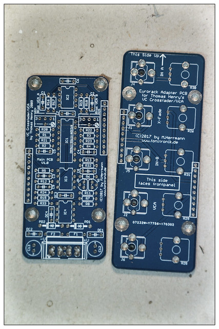
With the kind permission of Mr Thomas Henry i will offer PCBs and front panels for the VC Crossfader/VCA soon. The prototype PCBs arived just today:

VCXFaderVCA by Matthias Herrmann, on Flickr
_________________

cheers,
matthias
____________
Big Boss at fonitronik
Tech Buddy at Random*Source |
|
|
Back to top
|
|
 |
fonik

Joined: Jun 07, 2006
Posts: 3950
Location: Germany
Audio files: 23
|
 Posted: Sun Jul 09, 2017 5:55 am Post subject: Posted: Sun Jul 09, 2017 5:55 am Post subject:
|
  |
|
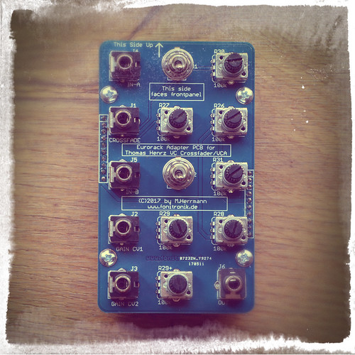
okay, i decided to do a 12HP version, offering attenuators for all inputs and the AC/DC switches. believe me, you really want all those attenuators!

TH VC FaderVCA by Matthias Herrmann, on Flickr
_________________

cheers,
matthias
____________
Big Boss at fonitronik
Tech Buddy at Random*Source |
|
|
Back to top
|
|
 |
fonik

Joined: Jun 07, 2006
Posts: 3950
Location: Germany
Audio files: 23
|
|
|
Back to top
|
|
 |
nhouse
Joined: Apr 05, 2020
Posts: 3
Location: italy
|
 Posted: Sun May 03, 2020 1:34 pm Post subject: Posted: Sun May 03, 2020 1:34 pm Post subject:
|
  |
|
Hi Fonik. great work indeed from a great TH schematics! the post is a bit old but i was tryng to understand the magic and following the work. mr TH's schematics are based on -+15V supplied, you use -+12V but i don't understand how you get those 12V?
i am missing something!
having hard life to upload the IMG so i will drop it here
https://imagizer.imageshack.com/v2/618x336q90/923/75KgIn.png |
|
|
Back to top
|
|
 |
elmegil

Joined: Mar 20, 2012
Posts: 2179
Location: Chicago
Audio files: 16
|
 Posted: Sun May 03, 2020 2:38 pm Post subject: Posted: Sun May 03, 2020 2:38 pm Post subject:
|
  |
|
It is a Eurorack module, whose system power is already +/- 12V.
Is that what you're asking, where the 12V comes from? |
|
|
Back to top
|
|
 |
nhouse
Joined: Apr 05, 2020
Posts: 3
Location: italy
|
 Posted: Sun May 03, 2020 3:17 pm Post subject: Posted: Sun May 03, 2020 3:17 pm Post subject:
|
  |
|
nope, i'm aware of that.
i posted a url with fonik vca's schematic and i read that at the beginning (from the header)the voltage is +-15V and after some the caps it becomes +-12V.
actually pin 1-2 of the Eurorack header should provide the -12V and the 9-10 the +12V .
it just confuses me |
|
|
Back to top
|
|
 |
elmegil

Joined: Mar 20, 2012
Posts: 2179
Location: Chicago
Audio files: 16
|
 Posted: Sun May 03, 2020 3:52 pm Post subject: Posted: Sun May 03, 2020 3:52 pm Post subject:
|
  |
|
| I suspect it's an oversight in revising the schematic, since the original was 15V. |
|
|
Back to top
|
|
 |
nhouse
Joined: Apr 05, 2020
Posts: 3
Location: italy
|
 Posted: Sun May 03, 2020 4:08 pm Post subject: Posted: Sun May 03, 2020 4:08 pm Post subject:
 |
  |
|
| ok .this is what i think too. but i needed to double check!=) |
|
|
Back to top
|
|
 |
|

