| Author |
Message |
LektroiD

Joined: Aug 23, 2008
Posts: 1019
Location: Scottish Borders
Audio files: 2
G2 patch files: 2
|
 Posted: Sun Jan 06, 2013 3:23 pm Post subject: Posted: Sun Jan 06, 2013 3:23 pm Post subject:
|
  |
|
I was running these modules at 12V, and just had another idea to increase to 15V, although it made no difference, I thought I'd mention it.
Can someone explain to me the sync line that I need to ground...
_________________
LektroiD |
|
|
Back to top
|
|
 |
diablojoy

Joined: Sep 07, 2008
Posts: 809
Location: melbourne australia
Audio files: 11
|
| Posted: Sun Jan 06, 2013 5:35 pm Post subject:
|
|
|
well you could try a 100K resistor to ground on the sync in jack
_________________
In an infinite universe one might very well
ask where the hell am I
oh yeah thats right the land of OZ
as good an answer as any |
|
|
Back to top
|
|
|
diablojoy
Joined: Sep 07, 2008
Posts: 809
Location: melbourne australia
Audio files: 11
|
| Posted: Sun Jan 06, 2013 5:52 pm Post subject:
|
|
|
hmm actually there should be one on the board already that does that job
have to check the schematic.
edit: ok there actually isn't
wrongre-edit : try a 100K sync jack side of R31 to ground just kludge it on top or just on the sync in jack itself , shouldn't hurt anything and may just solve your issue ... very maybe edit yet again :wrong ah thomas you clever man
ignore this bit it will effect the sync circuit pulse length perhaps in a bad way
re-re-re-edit : because i overthink everything
just ground your sync jack input to test out this theory first. edit :then see my next post for a more certain way.
_________________
In an infinite universe one might very well
ask where the hell am I
oh yeah thats right the land of OZ
as good an answer as any
Last edited by diablojoy on Mon Jan 07, 2013 1:04 am; edited 1 time in total |
|
|
Back to top
|
|
|
diablojoy
Joined: Sep 07, 2008
Posts: 809
Location: melbourne australia
Audio files: 11
|
| Posted: Mon Jan 07, 2013 12:43 am Post subject:
|
|
|
Had a bit more of a think about this on the drive home from work
To prove conclusively if the fault is in the sync circuitry or not
Remove the 4046 from its socket and very carefully bend pin 5 out so that when the chip is reinserted into the socket pin 5 will not connect through
then attach a short lead to ground to pin 5 with a small alligator clip or solder it temporarily.
fire the module back up and see if the VCO is stable now or not
if the VCO is now stable we can go from there [ not too much to check] if it still not stable at least we now know its not the sync circuitry.
_________________
In an infinite universe one might very well
ask where the hell am I
oh yeah thats right the land of OZ
as good an answer as any |
|
|
Back to top
|
|
|
LektroiD
Joined: Aug 23, 2008
Posts: 1019
Location: Scottish Borders
Audio files: 2
G2 patch files: 2
|
| Posted: Mon Jan 07, 2013 11:07 am Post subject:
|
|
|
I soldered a 100K resistor between the two wired pins on the sync socket. It made no difference. I'll try lifting & grounding pin 5 on the 4046 next and let you know if that sorts anything
_________________
LektroiD |
|
|
Back to top
|
|
|
fonik

Joined: Jun 07, 2006
Posts: 3950
Location: Germany
Audio files: 23
|
| Posted: Tue Jan 08, 2013 5:53 am Post subject:
|
|
|
it still gets me thinking: this cannot be a common failure due to a cold solder joint, or a single bad cap in the sync circuitry. these would be singularities and would not cause 4 VCOs to get bad over time...
it has to be an error that applies to all four builds.
so it has to be something that you used or did for all four VCOs (parts?). this thread has become so long overt time so i cannot remember: did you use the same parts from the same batches for all VCOs?
_________________

cheers,
matthias
____________
Big Boss at fonitronik
Tech Buddy at Random*Source |
|
|
Back to top
|
|
|
fonik
Joined: Jun 07, 2006
Posts: 3950
Location: Germany
Audio files: 23
|
| Posted: Tue Jan 08, 2013 5:55 am Post subject:
|
|
|
| diablojoy wrote: | | re-re-re-edit : because i overthink everything |

my quote of the day!
_________________
cheers,
matthias
____________
Big Boss at fonitronik
Tech Buddy at Random*Source |
|
|
Back to top
|
|
|
LektroiD
Joined: Aug 23, 2008
Posts: 1019
Location: Scottish Borders
Audio files: 2
G2 patch files: 2
|
| Posted: Tue Jan 08, 2013 6:03 am Post subject:
|
|
|
| fonik wrote: | it still gets me thinking: this cannot be a common failure due to a cold solder joint, or a single bad cap in the sync circuitry. these would be singularities and would not cause 4 VCOs to get bad over time...
it has to be an error that applies to all four builds.
so it has to be something that you used or did for all four VCOs (parts?). this thread has become so long overt time so i cannot remember: did you use the same parts from the same batches for all VCOs? |
Yes, I built them as a batch. This is why I'm considering it to be a component failure. Once I find the culprit, I am 99.99999% convinced it will be the same faulty part on all boards... I'm thinking maybe I didn't do a very good job of hand matching the transistors; I'm still awaiting the SSM2210's. I'm also going to try different tempcos (the ones I used are SMD).
_________________
LektroiD |
|
|
Back to top
|
|
|
Paradigm X
Joined: Feb 15, 2011
Posts: 363
Location: Null and void
Audio files: 2
|
|
|
Back to top
|
|
|
diablojoy
Joined: Sep 07, 2008
Posts: 809
Location: melbourne australia
Audio files: 11
|
| Posted: Tue Jan 08, 2013 2:17 pm Post subject:
|
|
|
LektroiD
bit of a long shot but thought i should ask anyway . which way did you mount your matched pair of 2n3904's ?
are they facing each other or same direction - are your pinouts correct ?
not sure if this has been covered before
just read back through the main topic , page 11 Argitoth had an issue,
his first post could be construed to be maybe similar.
_________________
In an infinite universe one might very well
ask where the hell am I
oh yeah thats right the land of OZ
as good an answer as any |
|
|
Back to top
|
|
|
LektroiD
Joined: Aug 23, 2008
Posts: 1019
Location: Scottish Borders
Audio files: 2
G2 patch files: 2
|
|
|
Back to top
|
|
|
diablojoy
Joined: Sep 07, 2008
Posts: 809
Location: melbourne australia
Audio files: 11
|
| Posted: Tue Jan 08, 2013 10:33 pm Post subject:
|
|
|
OK that looks right to me , oh well it was just a thought .
nice method with the tranny mounting by the way, very neat
but the thermal paste being electrically conductive is possible [some are, though most are not and also to varying degree's, also some are capacitive {a few pico farads}] . It should say if it is on the packaging .
_________________
In an infinite universe one might very well
ask where the hell am I
oh yeah thats right the land of OZ
as good an answer as any |
|
|
Back to top
|
|
|
fonik
Joined: Jun 07, 2006
Posts: 3950
Location: Germany
Audio files: 23
|
| Posted: Wed Jan 09, 2013 1:49 am Post subject:
|
|
|
| LektroiD wrote: | | I'm now wondering if the thermal paste on the tempco has become conductive... |
that's an idea.
i did a quick search in the net, and the whole topic is a known issue for those PC guys.
allmost all thermal pastes are conductive, especially the ones with silver in there. paste with zink oxyde is less conductive (but it still is).
however, there is non-conductive thermal paste available for PC users.
_________________
cheers,
matthias
____________
Big Boss at fonitronik
Tech Buddy at Random*Source |
|
|
Back to top
|
|
|
fonik
Joined: Jun 07, 2006
Posts: 3950
Location: Germany
Audio files: 23
|
| Posted: Wed Jan 09, 2013 1:51 am Post subject:
|
|
|
BTW great idea how you mounted the transistors. never seen this before. very elegant!
i think for future PCB layouts i will keep the super-matched-pairs footprint and use yout method for assembling hand matched transistors.
_________________
cheers,
matthias
____________
Big Boss at fonitronik
Tech Buddy at Random*Source |
|
|
Back to top
|
|
|
inlifeindeath

Joined: Apr 02, 2010
Posts: 316
Location: Albuquerque, NM
|
| Posted: Wed Jan 09, 2013 1:08 pm Post subject:
|
|
|
also, there's a run of 2n3904 with a C suffix (IIRC) that have a different pinout. i had this issue a few years ago.
_________________
http://www.youtube.com/user/borisandfef |
|
|
Back to top
|
|
|
blue hell
Site Admin

Joined: Apr 03, 2004
Posts: 24505
Location: The Netherlands, Enschede
Audio files: 298
G2 patch files: 320
|
| Posted: Wed Jan 09, 2013 1:26 pm Post subject:
|
|
|
Thermal paste  FTW! FTW!
Of course .. that's it
Anyway, seems very likely.
_________________
Jan
also .. could someone please turn down the thermostat a bit.
 |
|
|
Back to top
|
|
|
diablojoy
Joined: Sep 07, 2008
Posts: 809
Location: melbourne australia
Audio files: 11
|
| Posted: Wed Jan 09, 2013 2:50 pm Post subject:
|
|
|
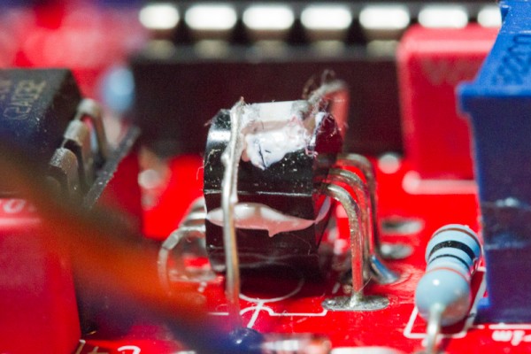
if it is the thermal paste being electrically conductive, being smeared all over the smt tempco like that would basically short it out , that would definitely cause a whole bunch of variation with the frequency over time and fits the bill for the most likely cause given the symptoms.
easy to check if a bit tedious cleaning every trace of all that paste off.
for an idea once you get your 2210's
my preferred method till now has been with socketed ssm2210 with the tempco underneath inside the socket, I either melt a couple of slots in the ends of the socket for the leads or use 2 rows of machined SIL pins , means the chip is still easily removed if need be , but you do have to get the height of the tempco right very slightly above the socket height and with a little extra length on the leads which gives the tempco some spring to press against the underside of the chip. With an smt tempco as you have used this should work fairly well as there will be good surface contact and temp changes from stray cool air is minimised by the socket body and chip
thermal paste should not be needed at all in that case.
_________________
In an infinite universe one might very well
ask where the hell am I
oh yeah thats right the land of OZ
as good an answer as any |
|
|
Back to top
|
|
|
LektroiD
Joined: Aug 23, 2008
Posts: 1019
Location: Scottish Borders
Audio files: 2
G2 patch files: 2
|
| Posted: Wed Jan 09, 2013 3:48 pm Post subject:
|
|
|
Well I de-soldered the tempco, wiped off the thermal paste, and re-soldered it. I have allowed it to run for a few hours to hopefully stabilise before making any dependable tests.
Now the wave does not jump around like crazy like it did (jerking from one frequency to another like a demented sample and hold unit). However the pitch is increasing and decreasing gradually like there's a really slow and subtle LFO controlling the pitch. So omitting the paste seems to have alleviated the main problem, but it's not cured it completely. Better, but still not usable...
_________________
LektroiD |
|
|
Back to top
|
|
|
Ralphperez
Joined: Jan 05, 2013
Posts: 3
Location: Virginia
|
| Posted: Thu Jan 10, 2013 12:47 am Post subject:
Re: 4046 Oscillators progressively getting worse over time |
|
|
| LektroiD wrote: | | Two of my oscillators are stable (at least as stable as an analog oscillator is going to get), but the other two are sounding rather ill, I have no idea why. They started off in good tune, but one went unstable after about 6 months, and now the second one... Is it only a matter of time before the others go? Maybe someone [url=http://www.niceledlights.com]led lighting[/url] can help me out. I attached an audio file of a direct square output, although all waveforms are doing the same wonky output.... |
There is some loose connection which is disturbing the supply of current.
Last edited by Ralphperez on Thu Jan 10, 2013 8:18 am; edited 1 time in total |
|
|
Back to top
|
|
|
Uncle Krunkus
Moderator

Joined: Jul 11, 2005
Posts: 4761
Location: Sydney, Australia
Audio files: 52
G2 patch files: 1
|
| Posted: Thu Jan 10, 2013 3:20 am Post subject:
|
|
|
Wouldn't you get more accurate tracking by sandwiching the tempco between the transistors? 
You really want the tempco to be enveloped by the temperature of both transistors. As it is, one side of the tempco is tracking one transistor, and the other side is tracking the air temperature above it. The temp of the lower transistor is probably not affecting the tempco very much at all.
I'd clean all the paste off everything, butt the tempco leads off the ends to keep it nice and slim, and put it between the transistors. Keep the position of the transistors almost the same as it is, just bend the lower one down slightly, upper one up slightly, thus making a very thin slot between them for the tempco.
_________________
What makes a space ours, is what we put there, and what we do there. |
|
|
Back to top
|
|
|
prgdeltablues
Joined: Sep 25, 2006
Posts: 222
Location: UK
Audio files: 12
|
| Posted: Thu Jan 10, 2013 6:55 am Post subject:
|
|
|
Sounds like you have solved the main problem!
You could also make a cover for the transistors/tempco out of expanded polystyrene. How slow and subtle are the changes you're still hearing? If you've got the module out on a bench, could just be caused by drafts.
Peter |
|
|
Back to top
|
|
|
diablojoy
Joined: Sep 07, 2008
Posts: 809
Location: melbourne australia
Audio files: 11
|
| Posted: Thu Jan 10, 2013 1:30 pm Post subject:
|
|
|
seems like uncle's answer has covered it all rather well.
_________________
In an infinite universe one might very well
ask where the hell am I
oh yeah thats right the land of OZ
as good an answer as any |
|
|
Back to top
|
|
|
LektroiD
Joined: Aug 23, 2008
Posts: 1019
Location: Scottish Borders
Audio files: 2
G2 patch files: 2
|
| Posted: Thu Jan 10, 2013 3:55 pm Post subject:
|
|
|
Well, I got one working, after cleaning the thermal paste from the tempcos (I left the paste sandwiched between the transistors). The fluctuations looked huge on the scope, but in fact they were minuscule when I linked them up to audio.
The other 3 have developed other faults somehow in all the messing about...
Oscillator 1:
Random pitches prevail, and added to the calamity, the Pulse Width dial also acts as a pitch control (in reverse).
Oscillator 2:
Same as oscillator 1, except the pitch is more stable, same problem with the Pulse Width affecting the pitch.
Oscillator 3:
Nothing happens until you turn the pitch dial round to 3 O'Clock, then a fixed high frequency sound is present - pushing the dial further round makes no effect, neither does the fine tune. Again, the Pulse Width does control pitch, this time in the standard orientation (clockwise for higher).
Oscillator 4:
Working ok.
I'm wondering in all the fiddling around if I've possibly done something to the PW part of the circuit which is causing the rest of the circuit to malfunction. I understand this is on the smaller PCB, so I will detach that from the main board and run the tests again...
_________________
LektroiD |
|
|
Back to top
|
|
|
diablojoy
Joined: Sep 07, 2008
Posts: 809
Location: melbourne australia
Audio files: 11
|
| Posted: Thu Jan 10, 2013 4:24 pm Post subject:
|
|
|
| Quote: | | Well, I got one working, after cleaning the thermal paste from the tempcos (I left the paste sandwiched between the transistors). The fluctuations looked huge on the scope, but in fact they were minuscule when I linked them up to audio. |
ahh pretty good result then !
1&2 sound like a wiring issue with all the messing about as you say,
as well as No-1 needing some more cleaning perhaps, that gunk is fairly stubborn to get all of it off .
No-3 sounds like possibly the 4046 and again possibly the same wiring issue.
you seem to be getting real close now though.
_________________
In an infinite universe one might very well
ask where the hell am I
oh yeah thats right the land of OZ
as good an answer as any |
|
|
Back to top
|
|
|
LektroiD
Joined: Aug 23, 2008
Posts: 1019
Location: Scottish Borders
Audio files: 2
G2 patch files: 2
|
| Posted: Thu Jan 10, 2013 5:43 pm Post subject:
|
|
|
| diablojoy wrote: | | Quote: | | Well, I got one working, after cleaning the thermal paste from the tempcos (I left the paste sandwiched between the transistors). The fluctuations looked huge on the scope, but in fact they were minuscule when I linked them up to audio. |
ahh pretty good result then !
1&2 sound like a wiring issue with all the messing about as you say,
as well as No-1 needing some more cleaning perhaps, that gunk is fairly stubborn to get all of it off .
No-3 sounds like possibly the 4046 and again possibly the same wiring issue.
you seem to be getting real close now though. |
I forgot to mention, I also swapped out the 4046 for a spare on all boards, it didn't seem to affect anything. I didn't change any wiring (bear in mind these were all working perfectly when I first built them - before the paste turned sour)...
_________________
LektroiD |
|
|
Back to top
|
|
|
|

 Forum index » DIY Hardware and Software » fonik's place