| Author |
Message |
NOISEBOB

Joined: Oct 13, 2019
Posts: 33
Location: NOISE
|
 Posted: Wed Mar 31, 2021 1:31 pm Post subject:
Re: PWM with a single XOR gate Posted: Wed Mar 31, 2021 1:31 pm Post subject:
Re: PWM with a single XOR gate
Subject description: can easily be added to a CD4046 VCO |
  |
|
| PHOBoS wrote: | here's a method which I thought up while trying to sleep. (I count electrons not sheep).
I have a CD4046 VCO wired up with it's output (pin4) connected to the Internal Phase Comparator I (pin3), which is just an XOR. And at some
point I wondered what happens if you connect the output of the VCO to the signal input (pin14) which is the other input of the XOR. Well that
would mean that the inputs of the XOR are just shorted together and therefor it's output will always stay low. So not very intersting,..
But that got me thinking,. what if I delay one input ? Then the inputs would be different from each other for a short time and therefor it's output
will also be high for a moment. In other words I can control the pulse width.  A simple adjustable delay can be made with a potentiometer and A simple adjustable delay can be made with a potentiometer and
a capacitor, and by adding a diode parallel to the potentiometer, the capacitor will get discharged instantly when the input goes low and so will
the output.
I did expect one problem, that is without a schmitt trigger input such a simple delay might not work so well, and cause unwanted oscillations.
So I just breadboarded it but I had to use an external XOR (CD4070) because I have the VCO build on a PCB and only made the XOR output
available. Well, it works perfect.  And the diode seems to take care of the unwanted behaviour I expected, without it I do see and hear some And the diode seems to take care of the unwanted behaviour I expected, without it I do see and hear some
extra oscillations.
The maximum 'on-time' is the same as the input signal and since the CD4046 has a pulse width of 50% I can't set it longer than
that. So with the right capacitor (dependent on the frequency) it's adjustable from 0 to 50%. But soundwise making it longer would sound
the same anyway. a 500K pot and 10nF capacitors seem to work nice.
fun fact: when I tried to adjust the circuit to work with NAND gates, I ended up with the same circuit I posted before.  |
.... if you then do the same trick again, but with an inverter on top, you get total pw control!
i think |
|
|
Back to top
|
|
 |
ianbax
Joined: Apr 20, 2022
Posts: 42
Location: Sheffield, UK
|
Posted: Mon Apr 25, 2022 6:27 am Post subject:
Re: PWM with a single XOR gate
Subject description: can easily be added to a CD4046 VCO |
|
|
| PHOBoS wrote: | here's a method which I thought up while trying to sleep. (I count electrons not sheep).
I have a CD4046 VCO wired up with it's output (pin4) connected to the Internal Phase Comparator I (pin3), which is just an XOR. And at some
point I wondered what happens if you connect the output of the VCO to the signal input (pin14) which is the other input of the XOR. Well that
would mean that the inputs of the XOR are just shorted together and therefor it's output will always stay low. So not very intersting,..
But that got me thinking,. what if I delay one input ? Then the inputs would be different from each other for a short time and therefor it's output
will also be high for a moment. In other words I can control the pulse width. A simple adjustable delay can be made with a potentiometer and
a capacitor, and by adding a diode parallel to the potentiometer, the capacitor will get discharged instantly when the input goes low and so will
the output.
I did expect one problem, that is without a schmitt trigger input such a simple delay might not work so well, and cause unwanted oscillations.
So I just breadboarded it but I had to use an external XOR (CD4070) because I have the VCO build on a PCB and only made the XOR output
available. Well, it works perfect. And the diode seems to take care of the unwanted behaviour I expected, without it I do see and hear some
extra oscillations.
The maximum 'on-time' is the same as the input signal and since the CD4046 has a pulse width of 50% I can't set it longer than
that. So with the right capacitor (dependent on the frequency) it's adjustable from 0 to 50%. But soundwise making it longer would sound
the same anyway. a 500K pot and 10nF capacitors seem to work nice.
fun fact: when I tried to adjust the circuit to work with NAND gates, I ended up with the same circuit I posted before. |
Hi! I've been experimenting with the circuit to achieve some PWM effects with my 4093 square waves.
It works great for low frequency triggers (100k pot 10uf cap) meaning I can go from tiny pulses to the full width of the original trigger. Super useful for triggering short notes.
But when I've tried to use it with audio range (100k pot, 100nf cap) I have a problem of there only being a limited range where the full pwm "phasing" or "beating oscillators" effect is noticeable.
I had more success with a high pass configuration (reversed from Phobos' schematic, so resistor to ground, cap in series). If I've understood correctly and using my scope this is because the filter that slows down the wave at lower frequencies doesn't slow it down enough and at too high a frequency cuts off altogether.
I've tried a couple of variations - 10k and 100nf in the filter for example. Or 47k and 22nf (just various combos I've got to hand) but all have the same problem.
Is this just an inherent limitation of that particular circuit? You can't get a filter that serves all frequencies? Would the sort of active filters built with 4069/4049 be better? e.g. https://hackaday.com/2015/03/25/logic-noise-filters-and-drums/
(these are on my to build list, but I wanted to get an oscillator design that I'm happy with going first). I know I could just breadboard it up but if someone can stop me going down a blind alley... |
|
|
Back to top
|
|
|
gabbagabi

Joined: Nov 29, 2008
Posts: 652
Location: Berlin by n8
Audio files: 23
|
|
|
Back to top
|
|
|
PHOBoS

Joined: Jan 14, 2010
Posts: 5884
Location: Moon Base
Audio files: 709
|
| Posted: Thu May 05, 2022 12:51 pm Post subject:
|
|
|
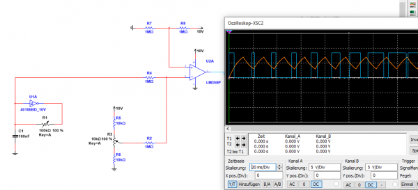
| gabbagabi wrote: | opamp  lunetta lunetta
 |
I'll allow it (can't speak for anyone else)
Although it's not a clean triangle but something a bit more exponential, it should work I think. neat.
I'd just use the non-inverting input for the reference voltage though. An inverted output wouldn't really matter
and can easily be (re-)inverted anyway. Also easy to add CV to it.
_________________
"My perf, it's full of holes!"
http://phobos.000space.com/
SoundCloud BandCamp MixCloud Stickney Synthyards Captain Collider Twitch YouTube |
|
|
Back to top
|
|
|
gabbagabi
Joined: Nov 29, 2008
Posts: 652
Location: Berlin by n8
Audio files: 23
|
| Posted: Sun May 08, 2022 6:54 am Post subject:
|
|
|
Ok, with permission granted i feel better😘
Thx
I remember vaguely, back in the days .... (Where I barely understood an opamps work)😃 that I had some trouble on the yusynth VCO PWM, which Mixes the CVs on the non inverting input.
Then I saw the Formant PWM , which uses the inverting input for Signal and the two CVs, lokked easy and elegand, tryed, worked well, since then I always use this topology.
Always happy to "see" you and the guys still around here
Gaby |
|
|
Back to top
|
|
|
synaesthesia

Joined: May 27, 2014
Posts: 291
Location: Germany
Audio files: 85
|
| Posted: Mon May 09, 2022 5:17 am Post subject:
|
|
|
| PHOBoS wrote: | | gabbagabi wrote: | opamp lunetta
|
I'll allow it (can't speak for anyone else) |
Plus One
Actually, all my current synth circuits use a mix of LM358 opams and CMOS gates at 5V unipolar supply, which is why I haven't posted anything for a long time. |
|
|
Back to top
|
|
|
PHOBoS
Joined: Jan 14, 2010
Posts: 5884
Location: Moon Base
Audio files: 709
|
| Posted: Mon May 09, 2022 11:15 am Post subject:
|
|
|
| Quote: | I remember vaguely, back in the days .... (Where I barely understood an opamps work)😃 that I had some trouble on the yusynth VCO PWM, which Mixes the CVs on the non inverting input.
Then I saw the Formant PWM , which uses the inverting input for Signal and the two CVs, lokked easy and elegand, tryed, worked well, since then I always use this topology. |
For a summing mixer yes, using the inverting input does have less drawbacks and is just easier to use.
For a comparator I don't think it matters much. it just compares the voltages on both inputs.
well in theory anyway with a perfect opamp, there might be some practical benefits I am not aware of.
To be clear, when I said "I'd just use the non-inverting input for the reference" I meant instead of the fixed voltage created with R7/R8.
| Quote: | Always happy to "see" you and the guys still around here
Gaby |
you're one of the guys 
I usually still check this forum multiple times a day just don't have much to post myself.
still building but have spend more time testing circuits (mostly for video) than finishing anything.
I also have a hard time getting parts right now so unfinished projects are piling up. 
_________________
"My perf, it's full of holes!"
http://phobos.000space.com/
SoundCloud BandCamp MixCloud Stickney Synthyards Captain Collider Twitch YouTube |
|
|
Back to top
|
|
|
|

 Forum index » DIY Hardware and Software » Lunettas - circuits inspired by Stanley Lunetta