Joined: Jan 14, 2010 Posts: 5872 Location: Moon Base
Audio files: 709
Posted: Thu Jan 05, 2017 5:56 pm Post subject:
New NANDulator kits are in stock
I made another batch of 10 and 2 have already been sold so there are 8 left at the moment. The amount in stock shown on the site is a bit lower
than I actually have because it only gets subtracted after I processed the order. So if there are multiple orders at once it could happen that they
are already out of stock while it doesn't yet say so on the site. By making the amount in stock a bit lower than I actually have there is a bit of a buffer.
Joined: Jan 14, 2010 Posts: 5872 Location: Moon Base
Audio files: 709
Posted: Fri Feb 03, 2017 5:07 pm Post subject:
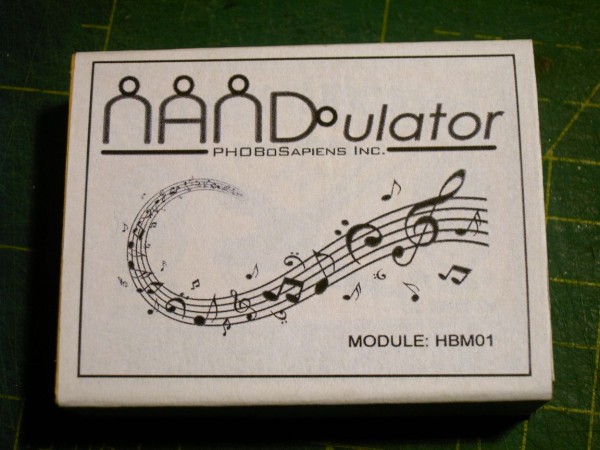
NANDulator HBM01 module
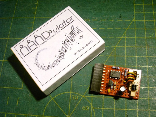
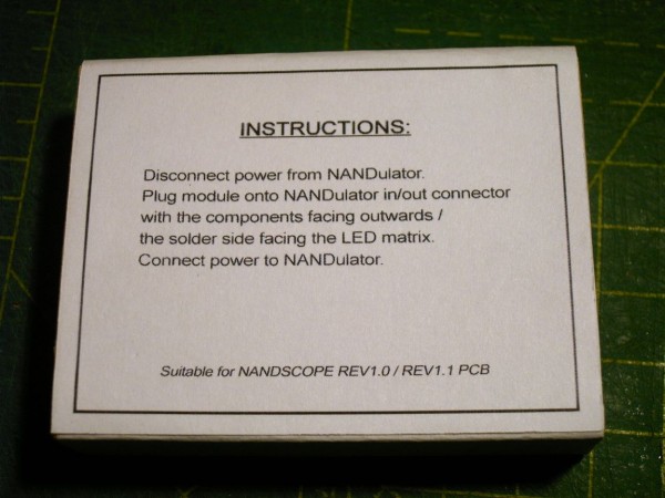
To celebrate robsol' s recent birthday I made him a little module that plugs onto the NANDulator and plays happy birthday through it.
It gets its power from the NANDulator and the happy birthday melody signal is connected to one of the inputs of Oscillator B so it
modulates the other oscillator build around the same NAND gate. Here's a video he made with it
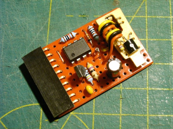
The circuit itself is actually pretty simple. The melody chip I used comes from a small candle that plays happy birthday when you light it.
It had two small metalized strips attached to it with some insulation between them and they melt together when the candle is lit.
I removed the strips and just bridged the 2 contacts together with a bit of solder which causes it to play continuously. It works on 1.5V
although it might be able to use a higher voltage, but I didn't test that. So the first part of the circuit is a LM317L voltage regulator to
create a 1.5V supply derived from the power of the NANDulator.
The output of the melody chip is a PWM squarewave but because it is powered by such a low voltage the signal is too low to
trigger the NAND gate. To fix this I used a comparator made with an opamp which also cleaned up the squarewave a bit.
Normally I'd use a voltage divider made with 2 resistors to set the reference voltage but because the NANDulator can take
a supply voltage from 9-12V it would also change this voltage. So instead I made use of the voltage drop over a diode to
create the reference voltage. 1 diode didn't work but 2 in series was just right. I used a dual opamp because of the pin layout
and wired the unused one as a voltage follower attached to whatever was most convenient which turned out to be pin 6.
here's the schematic and some photos of the module + packaging:
NANDulator module - HBM01.gif
Description:
NANDulator module: HBM01 schematic
Filesize:
32.13 KB
Viewed:
897 Time(s)
This image has been reduced to fit the page. Click on it to enlarge.
NANDulator HBM01 - 01.jpg
Description:
Filesize:
187.21 KB
Viewed:
723 Time(s)
This image has been reduced to fit the page. Click on it to enlarge.
NANDulator HBM01 - 02.jpg
Description:
Filesize:
226.46 KB
Viewed:
732 Time(s)
This image has been reduced to fit the page. Click on it to enlarge.
NANDulator HBM01 - 03.jpg
Description:
Filesize:
135.39 KB
Viewed:
709 Time(s)
This image has been reduced to fit the page. Click on it to enlarge.
NANDulator HBM01 - 04.jpg
Description:
Filesize:
118.46 KB
Viewed:
693 Time(s)
This image has been reduced to fit the page. Click on it to enlarge.
Joined: Jan 14, 2010 Posts: 5872 Location: Moon Base
Audio files: 709
Posted: Sun Feb 05, 2017 5:05 am Post subject:
Good to hear you are having fun with it
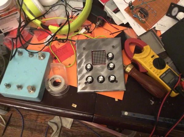
Did you remove the power connetor to make it fit ? I know that when I tried to design a plexiglass cover for it that was in the way.
The slide switch might also be a little bit high but you could easily replace it with a toggle or just leave it out althogether. To clean
up the cutout it would probably look really nice if you put some red transparent plastic on the inside, lighting gel would be ideal for this. _________________ "My perf, it's full of holes!" http://phobos.000space.com/ SoundCloudBandCampMixCloudStickney SynthyardsCaptain ColliderTwitchYouTube
I was not sure this was what I wanted, so I shaved the power connector down with a razor knife, same thing with the switch, scored it carefully with a razor knife, then cut it shorter with side cuts.
That made it fit without any major modification, just in case I decided I didn't like the idea.
I had another go on my nandulexor idea and it goes as follows:
send osc1&2 to exor. the result goes to exor with osc3, result goes to exor with osc 4, this result is the final signal.
additionally I took the caps of osc1&2 to a pot before going to ground.
this gives overall pitch control, but it also will cause a short and immediately blow the exor. I have to find a solution here.
connecting osc1&2 by their pot's middle pin gives a nice sync effect, here will be a switch.adding counters providing clock divide might come to mind next.
my goal is to make it create pitchy noisy rhythms...
this is the coolest project ever!
Joined: Jan 14, 2010 Posts: 5872 Location: Moon Base
Audio files: 709
Posted: Tue May 23, 2017 11:35 am Post subject:
hmm did you edit your post ? I remember something about using LEDs and I was going to mention that making an oscillator
with an XOR gate will probably not work. Yes, chaining XORs and oscillators can do some very interesting stuff
Not sure how adding pots in series with the capacitors actually works, it will limit the charging/discharging current but will
probably also act as a voltage divider which might cause some problems if the voltage stays between the treshold levels.
I don't know what is blowing the XORs unless you have a feedback loop without a resistor in between (don't attach the
output of a gate directly to its inputs). Anyway, good to hear you are experimenting with it as that is what I posted the circuit
for in the first place
thanks phobos!
I am really having a longtime blast with this.
I abandoned the exor and went for a 4017 instead.
The oscillator outputs are used to drive it (osc1 to clock, osc2 to reset, osc3 to enable). I make it run 4 steps only, driving a rgb led. funny colors at audio rate! these 4017 gates are then added to the osc gates. that brings interesting rhythms and sub-timbres.
I also (optionally with a switch) short the ins and outs directly at the chip with rgb leds. different positions yield different effects, I assume mostly by shorting gates and stealing voltage? so by stealing voltage/lowering pitch the led will give you focus on several rhythmical things...micky mouse logic at work!
Right now I am trying different things to have continuous modulations.
This might be a small env driven by a slow osc, bt no luck so far.
I also built some vactrols, but I have no luck slowing them down.
A example would be: 4017 step 1 goes through an led to a pot and then to the vactrol LED with a cap to ground and then an opamp buffer?
I am working on a schematic in easyEDA, but its my first one, so it looks still awful. One day I plan to make my own pcb, by using a schematic/pcb/provider solution, but it seems to be a long way..
I'm sure it's well known by nandulator experimenters but this *premier* circuit loves being voltage starved. Kinda like the ol' 40106 VCO that has a control voltage input to pin 14... the 4093 reacts very similar.
In my latest project I built two nadulators both with a pot that can swipe between supply voltage and and CV. Works very well when connected to my baby 8.
Further experimentation has led to me find the greatest weirdness when I drive the nandulator supply voltage off the output of a simple 4046 vco fed by all sorts of weird stuff. The 4046 output hits the first pole of my starve pot, pole 3 is Vss, and the center, pole 2, hits the power input to the chip. Very cool: numerous amazing values to found between the CV and Vss which all seem to filter, amaze, and bedazzle.
I feel a tad ashamed to bump an old thread but i've been sipping scotch. That, mixed with the recent high from building earlier today, has me typing. I don't think it's been mentioned but I'd argue it's an essential and easy mod to any future nandulator builds. _________________ home made noise and electronic ill-logic
Joined: Jan 14, 2010 Posts: 5872 Location: Moon Base
Audio files: 709
Posted: Sun Nov 12, 2017 2:47 pm Post subject:
Great idea , I actually never tried it myself. Because I have the simple LED scopes attached to it,
it would require some hacking. Did you buffer the output of the 4046 ? The circuit doesn't require much
current though so it's probably fine.
what if i put in a LDR instead of the 100k pots and 1k resistors on U1d and U1c? wouldn't that make for some crazy semi-uncontrollable noise?
yes, that would make it semi-uncontrollable
Not sure if it would be an improvement as small changes and the relation between the pot settings can make quite a difference,
but feel free to try it. An LDR connected to U1b works great, especially when used as a vactrol. _________________ "My perf, it's full of holes!" http://phobos.000space.com/ SoundCloudBandCampMixCloudStickney SynthyardsCaptain ColliderTwitchYouTube
Suggest you breadboard the idea, to confirm that this will make worthwhile sound.
As an engineering procedure it could be informative; I found that ldrs aren't that musically suited to NANDulators from my point of view, saving a lot of unnecessary building.
Suggest you breadboard the idea, to confirm that this will make worthwhile sound.
i did and it's wonderful/awful.
piedwagtail wrote:
As an engineering procedure it could be informative; I found that ldrs aren't that musically suited to NANDulators from my point of view, saving a lot of unnecessary building.
R
i think they are pretty good for rough beats when a flashing LED is added to it.........
i will need to breadboard a bit more as i'd also like to make it triggerable. by a sequencer or hitting a piezo disc.
Joined: Jan 14, 2010 Posts: 5872 Location: Moon Base
Audio files: 709
Posted: Sat Oct 26, 2019 10:39 am Post subject:
yep, for 'beats' they work great, not so much for tuning.
As for the schematic,. what you've drawn would function as a standard oscillator since pin 1 of the NAND gate is high at all times.
Your input can't really do anything apart from shorting out the supply if the pot is at a very low resistance. You could add a resistor
between pin 1 and +9V in which case it could function as a gated oscillator and the pot might adjust the treshold level a bit.
It wouldn't NANDulate though. _________________ "My perf, it's full of holes!" http://phobos.000space.com/ SoundCloudBandCampMixCloudStickney SynthyardsCaptain ColliderTwitchYouTube
You cannot post new topics in this forum You cannot reply to topics in this forum You cannot edit your posts in this forum You cannot delete your posts in this forum You cannot vote in polls in this forum You cannot attach files in this forum You can download files in this forum

 Forum index » DIY Hardware and Software » Lunettas - circuits inspired by Stanley Lunetta