| Author |
Message |
joshs
Joined: Dec 05, 2014
Posts: 32
Location: Home
|
 Posted: Thu May 07, 2015 6:22 pm Post subject:
Mixing/Amplifying Arduino Oscillators Posted: Thu May 07, 2015 6:22 pm Post subject:
Mixing/Amplifying Arduino Oscillators |
  |
|
| I'm building a DCO using the Arduino platform on an Atmega328. The plan is to do two oscillators and mix them together. So far it's working OK, but I'm looking for the "right way" to mix and amplify the signals... The setup that popped into mind was using a dual opamp and then just a regular pot with one oscillator output on each wiper and output from the center. Is that sensible? I could also use help figuring out how to design the opamp section... The Atmega328 is running at 5V, so 0-5V swings, but I probably want -/+5V... Can anyone point me to a circuit that could deal with that? Not sure how much of a difference it makes, but the output also isn't a normal analog output. I'm using wavetable synthesis with modulated PWM output... |
|
|
Back to top
|
|
 |
elmegil

Joined: Mar 20, 2012
Posts: 2179
Location: Chicago
Audio files: 16
|
|
|
Back to top
|
|
|
joshs
Joined: Dec 05, 2014
Posts: 32
Location: Home
|
| Posted: Thu May 21, 2015 12:19 pm Post subject:
|
|
|
I've made some decent progress on this. I have a circuit that works well enough, but I have been wildly guessing at some of the values and it'd be nice to get a little input on what sensible values might be or how to measure things to pick sensible values. I have a respectable analog 50mhz oscilloscope (only one channel for the moment and not meticulously calibrated) and a good DMM...
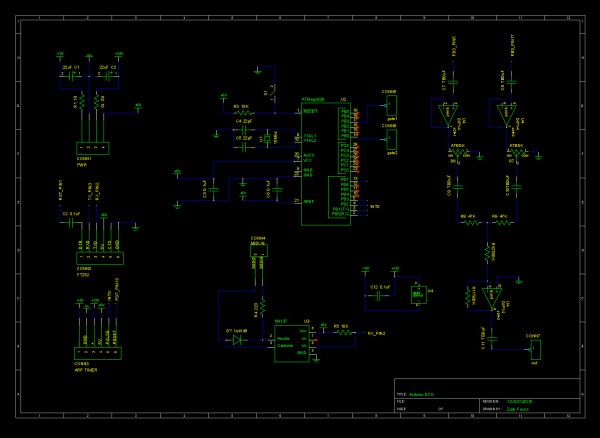
The schematic I'm including has an Arduino generating two waveforms using wavetable synthesis. The outputs aren't clean waves, but PWM emulations of the waves. However, this seems to work fine especially after filtering. On the oscilloscope after some filtering, the waves look right and go from ground to about +5v. One problem I've noticed is that if the input gets too high (pots at full volume) there is clipping of the signal. Which is weird to me, since when I've measured the output, it seems low, well under the +/-15 I thought it'd be capable of without distortion. I was going for roughly 10vpp. The clipping can sound kind of cool, but I'd rather have it under control and know why it's happening. The area I'd like feedback on is the part of the circuit diagrammed on the right side of the schematic. The top two inputs are directly connected to the PWM outputs on the ATMega328 chip (Pin 3 and 11 in Arduino land).
NOTE: Ignore the +/-12V, it's actually running at +/-15V
Here are the main area's I'm concerned about. The testing values all work enough to make sound, but perhaps there are other values I should try to improve performance?:
-C7/C8 are meant to remove the DC offset in the signal... I've used 0.1uF in testing
-R6/R7 control the level of each oscillator (i.e. PWM output)... I've used A500K in testing
-C9/10 are meant to remove any DC offset brought on by the buffer stage. I've used 0.1uF in testing
-R8/R9 are meant to reduce/block interference between the two oscillator circuits. I used 47K in testing
-*missing from schematic* is a capacitor from the junction of R8-R9 to ground meant to act as a lowpass filter to clean up the PWM signal. In testing I used 3.3nF
-R10/R11 are the feedback resistors for the op amp which is set up as an inverting amplifier. I tested at 110K in R10 and 470K in R11... which I figure is about 3x gain?
-C11 is the output coupling capacitor, it will connect directly to the jack on the panel. I used 22uF in testing a put the negative lead facing outward
Kind of a lot to take on, but I'll appreciate any input I get. I'll try and update this thread once I get to building so no one wastes time looking at a circuit that's already done  I can't imagine I'll have this thing built for at least a week or two. I can't imagine I'll have this thing built for at least a week or two.
| Description: |
|
| Filesize: |
201.92 KB |
| Viewed: |
674 Time(s) |
| This image has been reduced to fit the page. Click on it to enlarge. |
|
|
|
|
Back to top
|
|
|
Electric Druid

Joined: Mar 13, 2012
Posts: 44
Location: UK
|
| Posted: Mon Oct 19, 2015 5:01 pm Post subject:
|
|
|
There's a lot that I'd do differently on that RHS. I would:
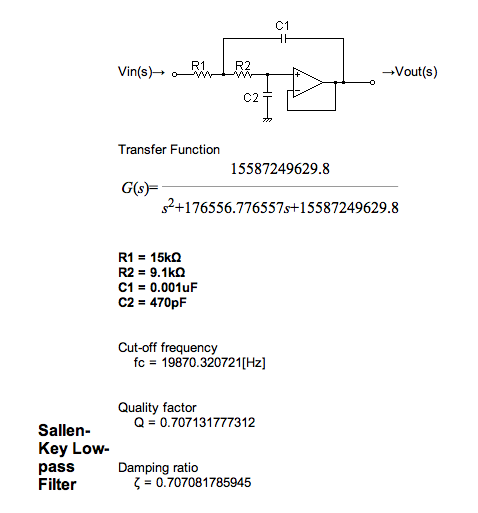
Replace the voltage followers with a 2-pole filters instead. These can be DC coupled, so don't worry about the AC-coupling caps before and after - they can go. The filter cutoff needs to be as low as you can go to remove as much PWM frequency as possible without damaging the highest audio frequency you'll make. 15KHz or 20KHz is probably a good mark.
Reduce the pots to much less so they don't load the following stage - 10K would be best, but 50K or 100K would probably do.
Replace R10 with a wire link. This makes this op-amp into a standard inverting mixer. I'd use 47K resistors for both the input resistors, and 100K for the feedback resistor. This gives x2 gain on both inputs (100/47 = 2.13). Since your inputs are 0-5V, each will be boosted to 0-10V, so your output could be as much as 0-20V on the peaks. Note that the output is inverted, so it'll be 0V to -20V.
Finally, we need to deal with the DC offsets, since 0-20V output isn't what we want. Each amplified 0-10V signal can be regarded as a +/-5V AC signal riding on top of a +5V DC offset, which becomes a -5V offset at the output.
Since we have two such offsets, we've got +10V DC to cancel out. Luckily you have a -12V supply, so we add another input to the mixer, this time with a 120K input resistor. This reduces the -12V to -10V, which is what we need to cancel the offsets.
HTH,
Tom
| Description: |
| Example 20KHz 2-pole filter (Sallen-Key Butterworth, IIRC) |
|
| Filesize: |
35.46 KB |
| Viewed: |
8380 Time(s) |
|
_________________
Electric Druid Synth and Pedal DIY website |
|
|
Back to top
|
|
|
|

 Forum index » Instruments and Equipment » Modular Synthesis
