| Author |
Message |
LeBon
Joined: Mar 23, 2015
Posts: 18
Location: USA
|
|
|
Back to top
|
|
 |
nuipb
Joined: Oct 06, 2009
Posts: 49
Location: France
|
 Posted: Wed Jan 05, 2022 12:12 pm Post subject: Posted: Wed Jan 05, 2022 12:12 pm Post subject:
|
  |
|
Thanks for the link to the sockets.
Of course correct me if I'm wrong but your explanation reads a little like "if it's there do leave it there, and if it's not there don't add it", therefore I don't really feel the need to say it, so why would you mention it ?
except of course in the case of the System-100 since I understand it's an original error...
For the record the RSF Expander has a 200k on pin 6. |
|
|
Back to top
|
|
|
LeBon
Joined: Mar 23, 2015
Posts: 18
Location: USA
|
| Posted: Wed Jan 05, 2022 3:38 pm Post subject:
|
|
|
As a rule of thumb, leave everything where they are and don't add anything else to the circuit, unless you know exactly what you're doing.
For the RSF, in order to calculate the resistor value, I need to know what is the voltage supply to pins 8 and 5.
For the minimoog, the initial copies of the new VCO board (the new design incorporating the uA726) came with a 75k resistor. They soon realized that it was wrong and quickly replaced it for the correct value of 49k9. Ironically, 75k is the value that appears on the datasheet example. My guess is that the VCO designer (which wasn't Bob Moog) didn't bother to calculate the resistor value and simply copied it from the datasheet.
For the System 100, replace the damaged uA726 with my circuit and calibrate the VCO as per manual. If it refuses to tune after the 3rd pass, replace the 82k resistor for a 174k and try again. If it still doesn't tune, then there is probably something wrong somewhere else in the circuit. If everything goes ok, post pictures of your synth board with the new replacement. We're making history here!
Last edited by LeBon on Thu Jan 06, 2022 10:27 am; edited 1 time in total |
|
|
Back to top
|
|
|
nuipb
Joined: Oct 06, 2009
Posts: 49
Location: France
|
|
|
Back to top
|
|
|
LeBon
Joined: Mar 23, 2015
Posts: 18
Location: USA
|
| Posted: Thu Jan 06, 2022 5:44 am Post subject:
|
|
|
In addition to the 4 .gbr files, you must send to the PCB manufacturer the drill file. File -> Export -> Drill data. Use the default parameters.
6V2 is a generic 6.2V zener diode, BZX79C6V2 or 1N753. |
|
|
Back to top
|
|
|
nuipb
Joined: Oct 06, 2009
Posts: 49
Location: France
|
| Posted: Thu Jan 06, 2022 6:07 am Post subject:
|
|
|
Thanks.
| LeBon wrote: | | 6V2 is a generic 6.2V zener diode, BZX79C6V2 or 1N753. |
So I understand my first link was right. |
|
|
Back to top
|
|
|
synthRodriguez
Joined: Jan 30, 2023
Posts: 1
Location: Piqua, OH
|
| Posted: Mon Jan 30, 2023 3:49 pm Post subject:
|
|
|
Thought I would chime in.
Working on a Korg Trident mkII that I thought had a bad UA726; turned out to be a broken via between the upper and lower layer. At any rate it does use a 75k heater resistor in its design.
It got me thinking though. I've worked on a lot of synths, but the Korg is my first with a 726. I do see a lot of people online finding dead ones/searching for replacements. How does the UA726 typically fail? Does the heater section die? One of the transistors? |
|
|
Back to top
|
|
|
mikefiction
Joined: Jan 23, 2013
Posts: 3
Location: Circleville, OH USA
|
| Posted: Sun Mar 24, 2024 1:56 am Post subject:
|
|
|
| LeBon wrote: |
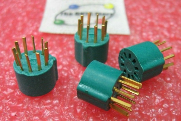
Here you go, a direct replacement PCB for the uA726. This PCB is plug'n'play, no adjustment is required. Calibrate your VCO as usual (or as per manual). Open the file with Sprint Layout 6.0.
The 49k9 resistor and the 10n capacitor were omitted, because they are part of the VCO board. The resistor is for temperature control and must be kept at 49k9 ± 1% for the minimoog. It may vary for other models. The current between the resistor and the rest of the circuit must be kept at 40 uA (microamperes) ± 1% for all applications requiring 1V/octave.
The 200R resistor is the current limiter for the heating transistor and must be kept at 200R ± 1% for all applications. All other resistors are ± 5%.
The funny thing about it is that the solution for the 726 problem was already there all the time, but for some reason nobody had noticed it. This trick can also be used on the Jupiter 8, VCS3, ARP Odyssey, ARP 2600, etc. For the ARP VCO, a CA3096 is used. |
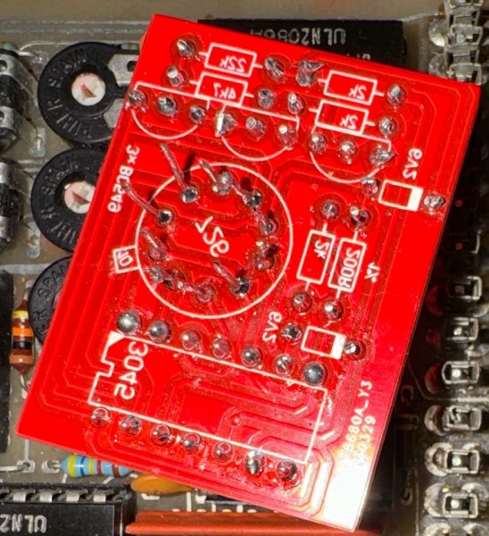
Sorry for reviving a 2 year old thread. Isn't this backwards?
Meaning it looks like the board would be installed component side down.
From the top, the ua726 pins go 1-2-3 etc counter-clockwise but this replacement board looks like it's 1-2-3 etc clockwise. If the component/silkscreen side is installed facing up, it looks like only pins 10 and 5 would be correct. Hope that makes sense.
I noticed it initially because the ua726 NC pin 7 is pin 3 on this PCB looking from above. |
|
|
Back to top
|
|
|
nuipb
Joined: Oct 06, 2009
Posts: 49
Location: France
|
| Posted: Sun Mar 24, 2024 3:41 am Post subject:
|
|
|
[quote="mikefiction"] | LeBon wrote: | Isn't this backwards?
Meaning it looks like the board would be installed component side down.
From the top, the ua726 pins go 1-2-3 etc counter-clockwise but this replacement board looks like it's 1-2-3 etc clockwise. If the component/silkscreen side is installed facing up, it looks like only pins 10 and 5 would be correct. Hope that makes sense.
I noticed it initially because the ua726 NC pin 7 is pin 3 on this PCB looking from above. |
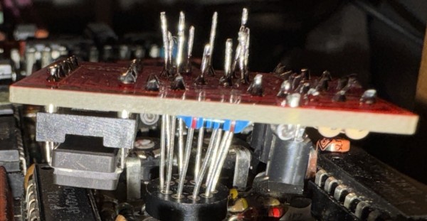
You are probably right as I tried it and so far it doesn't fully work. I'd be really interested if some of you could understand what is wrong and offer a fix...
| Description: |
|
| Filesize: |
356.61 KB |
| Viewed: |
187 Time(s) |
| This image has been reduced to fit the page. Click on it to enlarge. |
|
| Description: |
|
| Filesize: |
498.31 KB |
| Viewed: |
220 Time(s) |
| This image has been reduced to fit the page. Click on it to enlarge. |
|
|
|
|
Back to top
|
|
|
mikefiction
Joined: Jan 23, 2013
Posts: 3
Location: Circleville, OH USA
|
| Posted: Sun Mar 24, 2024 7:03 am Post subject:
|
|
|
| nuipb wrote: |
You are probably right as I tried it and so far it doesn't fully work. I'd be really interested if some of you could understand what is wrong and offer a fix... |
Your whole PCB looks like it was mirrored when created? I'm not familiar with Sprint as I use Diptrace, but I downloaded the demo to view the PCB. Did you accidentally check the 'mirror' option when you exported to gerber? That would explain what I'm seeing.
Comparing the schematic and referencing the datasheets of both devices everything else looked ok, just the pinouts of the ua726 were mirrored in the original. I've redrawn the board in diptrace and sent them off for fab, then noticed that error - corrected it and resent the new version off to fab. We'll see how it goes 
I also condensed it's size a little bit and i'm sure that could be optimized further too if this works.

I also noticed the schematic specifies BC546 and the PCB says BC549 - I'm not sure which is correct and haven't looked at the datasheets to see if it even matters yet. I'll check into that next. |
|
|
Back to top
|
|
|
nuipb
Joined: Oct 06, 2009
Posts: 49
Location: France
|
| Posted: Sun Mar 24, 2024 11:58 am Post subject:
|
|
|
I see what you mean and as far as I was aware of it I didn't "mirror" the drawing. Of course I could have made a mistake that day but doubt it. However I certainly hoped after delivery that the traces would be the other side around at least, so that the parts remain accessible.
I also thought of condensing the PCB once it fully works. My first suggestion would be to reduce the diameter of the UA726 imprint and make it the same diameter as the original. The current diameter is quite bigger and is a pain to assemble...
I'm certainly interested in your results. Please do keep us informed ! |
|
|
Back to top
|
|
|
|

 Forum index » DIY Hardware and Software