| Author |
Message |
Snaper
Joined: Feb 28, 2014
Posts: 217
Location: Hungary
|
 Posted: Thu Oct 22, 2015 10:43 pm Post subject:
Circuit trouble shooting request Posted: Thu Oct 22, 2015 10:43 pm Post subject:
Circuit trouble shooting request
Subject description: Circuit trouble shooting request |
  |
|
Hi Guys,
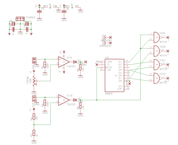
Just etched the below circuit, and worked great, but now, works only randomly...I mean, sometimes works like a charm, after a few secs, nothing...
Things what I've checked and what you should know :
- used a 4081, not a 4011 as shown in the schemo
- I've accidentally reversed polarity during the very first start, but right after, everything worked fine, maybe thats the reason of the random working of the CMOSs...
- checked the voltages, no negative voltages, clock is fine, data is fine, everything should be fine 
Still don't know what could be the problem, maybe that polarity reverse killed the chips, unfortunately, I don't have more, and today is National Holiday in Hungary...
| Description: |
|
| Filesize: |
37.53 KB |
| Viewed: |
230 Time(s) |
| This image has been reduced to fit the page. Click on it to enlarge. |
|
|
|
|
Back to top
|
|
 |
synaesthesia

Joined: May 27, 2014
Posts: 291
Location: Germany
Audio files: 85
|
| Posted: Fri Oct 23, 2015 12:20 am Post subject:
|
|
|
| Hi Snaper, what about OE at pin 15? It isn't connected in your schematic, but it has to be tied to Vdd to see any outputs from the 4094. |
|
|
Back to top
|
|
|
Snaper
Joined: Feb 28, 2014
Posts: 217
Location: Hungary
|
| Posted: Fri Oct 23, 2015 1:21 am Post subject:
|
|
|
| synaesthesia wrote: | | Hi Snaper, what about OE at pin 15? It isn't connected in your schematic, but it has to be tied to Vdd to see any outputs from the 4094. |
Yeah, that could be a problem.
And I think Strobe should be to Vdd too.
Could somebody confirm?
But why does it work sometimes? |
|
|
Back to top
|
|
|
synaesthesia
Joined: May 27, 2014
Posts: 291
Location: Germany
Audio files: 85
|
| Posted: Fri Oct 23, 2015 9:04 am Post subject:
|
|
|
Strobe goes to SW2 according to your schematic. If that switch is ever open and strobe is not connected, you should add a pull-up or pull-down resistor of 100K.
Edit: Ah, I guess SW2 refers to the cross below then. The fact that you are using crosses (usually no-connect) for patch contacts confused me here. Strobe can be tied directly to Vdd then.
Your circuit would work without OE or STR connected whenever static electricity provides a sufficient high level to that high-impedance input pin. Just touching it can change that. |
|
|
Back to top
|
|
|
gdavis
Joined: Feb 27, 2013
Posts: 359
Location: San Diego
Audio files: 1
|
| Posted: Fri Oct 23, 2015 9:38 am Post subject:
|
|
|
| Snaper wrote: | | synaesthesia wrote: | | Hi Snaper, what about OE at pin 15? It isn't connected in your schematic, but it has to be tied to Vdd to see any outputs from the 4094. |
Yeah, that could be a problem.
And I think Strobe should be to Vdd too.
Could somebody confirm?
But why does it work sometimes? |
Inputs should never be allowed to "float". Digital inputs should always be connected to a logic 1 or 0. If the input is unused, it should be tied to VDD or GND as appropriate. As synaesthesia mentioned, an unconnected input will drift depending on the surrounding electrical environment and can appear to randomly switch on or off.
STR and OE should both be tied to VDD.
If SW1 and SW2 are the two connections of a switch that can be either open or closed, you should put a pull-up or pull-down on the D pin or you could have problems with that as well (D pin will be floating when the switch is open). There is a 10k pull-down on the SW1 side, but that doesn't do you any good on the D pin when the switch is open.
_________________
My synth build blog: http://gndsynth.blogspot.com/ |
|
|
Back to top
|
|
|
Snaper
Joined: Feb 28, 2014
Posts: 217
Location: Hungary
|
| Posted: Fri Oct 23, 2015 9:59 am Post subject:
|
|
|
| gdavis wrote: | | Snaper wrote: | | synaesthesia wrote: | | Hi Snaper, what about OE at pin 15? It isn't connected in your schematic, but it has to be tied to Vdd to see any outputs from the 4094. |
Yeah, that could be a problem.
And I think Strobe should be to Vdd too.
Could somebody confirm?
But why does it work sometimes? |
Inputs should never be allowed to "float". Digital inputs should always be connected to a logic 1 or 0. If the input is unused, it should be tied to VDD or GND as appropriate. As synaesthesia mentioned, an unconnected input will drift depending on the surrounding electrical environment and can appear to randomly switch on or off.
STR and OE should both be tied to VDD.
If SW1 and SW2 are the two connections of a switch that can be either open or closed, you should put a pull-up or pull-down on the D pin or you could have problems with that as well (D pin will be floating when the switch is open). There is a 10k pull-down on the SW1 side, but that doesn't do you any good on the D pin when the switch is open. |
Thanks! |
|
|
Back to top
|
|
|
Snaper
Joined: Feb 28, 2014
Posts: 217
Location: Hungary
|
| Posted: Fri Oct 23, 2015 10:04 pm Post subject:
|
|
|
Tied EO and STROBE to Vdd and now "everything is awesome"!
Thanks for the help guys! |
|
|
Back to top
|
|
|
|

 Forum index » DIY Hardware and Software » Lunettas - circuits inspired by Stanley Lunetta
