| Author |
Message |
Grumble

Joined: Nov 23, 2015
Posts: 1320
Location: Netherlands
Audio files: 30
|
 Posted: Mon Nov 23, 2015 8:20 am Post subject:
arduino (clone) based modular synth Posted: Mon Nov 23, 2015 8:20 am Post subject:
arduino (clone) based modular synth
Subject description: this article writes about my idea to build an arduino(clone) based modular synth |
  |
|
recently I built an arduino (clone) based synth, but if I knew what I know now, I would have built a modular syth to start with.
So, now I'm thinking about and building my second synth, modular this time.
For that I'm using 5 basic components (besides the usual knobs, switches, connectors etc.)
1st. An Arduino clone based on the ATmega328P, this particular one is called the PRO MINI
This particular board also outputs ADC6 and ADC7 not available on the dip version of the Atmega328.
This board is very breadboard friendly, and I use dual sided thru plated (almost) eurocard sized experiment board.
2nd. I obtained several Direct Digital Synthesis chips, the Analog Devices AD9833 used for several purposes: It is capable to output a sine wave (12 bits accuracy, 0.6V p/p), a triangle 0.6V p/p and a square wave 5V p/p.
These three signals are NOT simultaneous available. I use the Triangle and Sine-waves as audio signals, and the Square wave as a clock signal.
By using PB0 on the Arduino as clock to the AD9833 the output frequency may be set to as low as ~0.06 Hz (which also is the minimum step size), so they are usable as an audio generator but also as a LFO without changing the input frequency.
By using the triangle wave and a variable voltage (potmeter or CV) to a comparator I am able to make pulses with a variable pulsewidth.
3rd. For filtering I use digital programmable filters e.g. MAX261 clocked by the Square output of one of the AD9833. The MAX261 has two filter sections, programmable Q-factor, LP, HP, Notch, a programmable input frequency divider, and a free usable opamp.
4th. For programming the ADSR I use a DAC MAX5122, again from Maxim, but this one is especially designed for used with sensors. The beauty in this DAC lies in that it can use an external REF voltage.
By doing this, the output is direct dependable form the REF input, which may be a voltage from a potentiometer, or a CV or even (with the aid of a capacitor) a LFO.
5th. The Arduino has (depending on the type of processor) 6 to 8 analog inputs, but sometimes I need more inputs to measure the potentiometer shaft positions or switch positions.
The chip I use to expand the number of analog inputs is a 16 channel analog multiplexer/demultiplexer 74HC4067, for 4 digital outputs and 1 (or two) analog inputs you get 16 analog inputs. |
|
|
Back to top
|
|
 |
Grumble
Joined: Nov 23, 2015
Posts: 1320
Location: Netherlands
Audio files: 30
|
| Posted: Wed Nov 25, 2015 1:39 am Post subject:
|
|
|
In the near future I plan to write some more about this ongoing project, with pictures, diagrams etc.
I hope this will work two ways: first maybe it is fun to read about my progress, or maybe to help someone out facing technical difficulties or presenting ideas how to technically solve certain problems.
Secondly, I would really like to have some input in what kind of inputs/outputs my designs "should" have.
I am confident in my knowledge about electronics, but am a novice in playing (with) and programming synthesizers.
You will notice that I'm using digital solutions as much as possible, because I think it is more flexible and it also is my hobby...
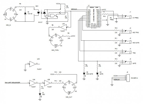
Starting point is my keyboard: I bought a Primax Midistorm keyboard on the internet for 15€. Inside the case of this keyboard there are two pcb's with about 32 keys each.
Enough to build 2 keyboards  using an Arduino using an Arduino
My keyboards are very basic polyphonic: it just gives a midi out (note on/channel, key number, velocity and note off/channel, key number, velocity=0).
By making the communication this easy the receiving part can be simple (and fast, to minimalise latency) to.
Inside my synth I use the midi input signal to get the part of the midi signal responsible for the note and distribute that to e.g. a digital programmable oscillator or filter.
Also I create a key-down signal: a digital signal that tells the rest of the synth that a key is pressed. |
|
|
Back to top
|
|
|
AuDioMiRage
Joined: Jan 14, 2015
Posts: 9
Location: Wisconsin
|
| Posted: Sun Nov 29, 2015 6:46 pm Post subject:
|
|
|
Looking forward to seeing more info on this project. I also am learnig to work with coding for Arduino and this seems like the perfect motivator project.
In the mean time, I'll start gathering up the parts. |
|
|
Back to top
|
|
|
Grumble
Joined: Nov 23, 2015
Posts: 1320
Location: Netherlands
Audio files: 30
|
| Posted: Wed Dec 02, 2015 1:16 am Post subject:
|
|
|
I am not using the Arduino IDE, I use Atmel Studio 7.
The good thing is that the Arduino IDE is integrated in the Atmel Studio 7. |
|
|
Back to top
|
|
|
Grumble
Joined: Nov 23, 2015
Posts: 1320
Location: Netherlands
Audio files: 30
|
|
|
Back to top
|
|
|
Grumble
Joined: Nov 23, 2015
Posts: 1320
Location: Netherlands
Audio files: 30
|
| Posted: Mon Feb 22, 2016 1:31 am Post subject:
|
|
|
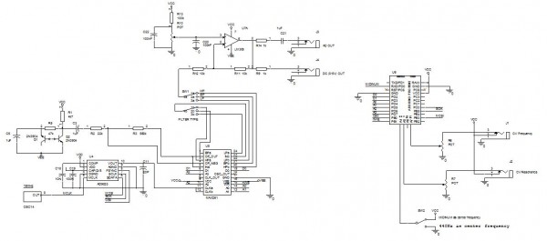
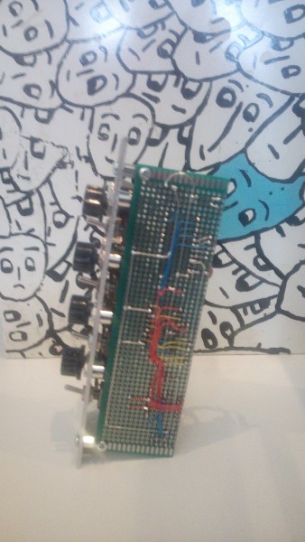
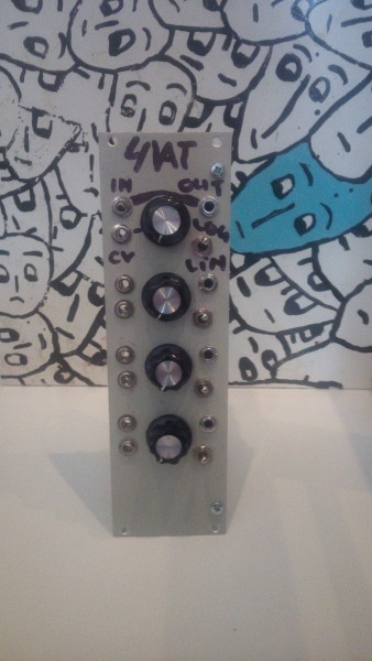
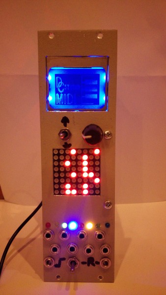
The next board finished is a noiseboard.
It has an (almost) standard transistor noise generator, a clock generator built from a AD9833 DDS chip which is clocked with 16MhZ, then the signal is amplified and fed thru a MAX261 programmable universal filter.
This makes it possible to choose with a three step rotary switch between a low pass, band pass and high pass filter.
Both the center frequency and the Q-factor of this filter are controllable by a potmeter and/or a control voltage (0 - 5V)
The advantage of using this filter is the reaction speed (about 1.5 mS) and it can be set to self-oscillating, which makes it a nice signal source.
The filter is followed by an amplifier to give the signal an amplitude of 0 - 5V and to lower the output impedance of the noise board.
Additionally there is a decoupling capacitor to have the noise swing around 0 V.
The DDS and Filter are controlled by an Improved Arduino Pro Mini.
A switch on the front panel lets you choose between a fixed base frequency, in a way that when the frequency knob is in center position the center frequency will be 440Hz, when the switch is in down position, and the frequency knob is in center position, the base frequency follows the midi signal.
There is one downside by using this filter and that is the bleed thru of the clock frequency when the filter is programmed for a low center frequency.
This filter is built using switching around capacitors and since the max division of the clock frequency is about 200x you start hearing a signal when the center frequency reaches about 40 or so Herz.
Link to the AD9833
Link to MAX261
Link to Arduino Pro Mini
edit: semantics and error in diagram
| Description: |
|
| Filesize: |
68.23 KB |
| Viewed: |
1530 Time(s) |
| This image has been reduced to fit the page. Click on it to enlarge. |
|
Last edited by Grumble on Thu Feb 25, 2016 4:18 pm; edited 2 times in total |
|
|
Back to top
|
|
|
Grumble
Joined: Nov 23, 2015
Posts: 1320
Location: Netherlands
Audio files: 30
|
| Posted: Mon Feb 22, 2016 1:37 am Post subject:
|
|
|
You will see more of the AD9833 DDS chip because I'm also using it on a signal generator board on which I use 4 of these.
They are capable of putting out a sine- triangle- and square wave signal (not at the same time). |
|
|
Back to top
|
|
|
Grumble
Joined: Nov 23, 2015
Posts: 1320
Location: Netherlands
Audio files: 30
|
|
|
Back to top
|
|
|
sixbyseven

Joined: Jan 28, 2016
Posts: 26
Location: hamilton, Ontario
|
| Posted: Fri Feb 26, 2016 6:00 am Post subject:
Arduino or ATMel based sythns. |
|
|
Awesome work Grumble. I too have been using atmel and ARM processors for a couple of synth projects. I am also using the AD9833 as waveform generators (along with a pro mini atmel328 as a controller).
I have never build a completed, modular type synth as most of the projects I do, consist of building small, specialized synths into "stand alone" musical instruments.
Really looking forward to see how your project turns out.
_________________
Young enough to enjoy techno, old enough to remember a Z80 and tiny-C. |
|
|
Back to top
|
|
|
Grumble
Joined: Nov 23, 2015
Posts: 1320
Location: Netherlands
Audio files: 30
|
| Posted: Fri Feb 26, 2016 6:32 am Post subject:
|
|
|
Thank you!
My first synth was a non modular synth (see the avatar) but if I knew then what I know now it would have been a modular. It's so much fun!
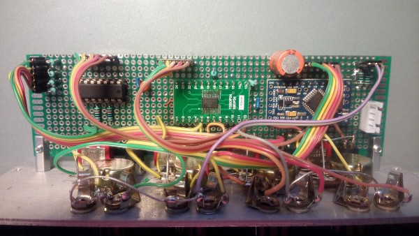
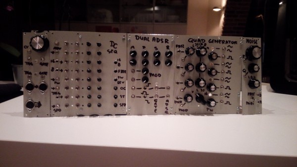
From the picture above this post only the midi module and the noise generator are finished, the rest is half built or complete pm 
First I want to have finished a complete usable synth before starting to build more "unusual" modules like sound processors, drum modules and the like.
So after the modules of this picture are finished I still need a (dual) vcf and a mixer with gain/offset possibilities. |
|
|
Back to top
|
|
|
Grumble
Joined: Nov 23, 2015
Posts: 1320
Location: Netherlands
Audio files: 30
|
|
|
Back to top
|
|
|
Grumble
Joined: Nov 23, 2015
Posts: 1320
Location: Netherlands
Audio files: 30
|
| Posted: Wed Mar 02, 2016 2:14 pm Post subject:
|
|
|
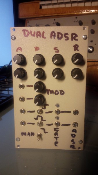
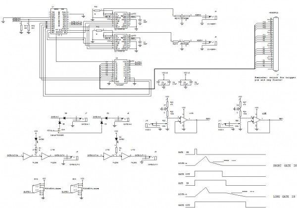
Next unit finished: Dual ADSR.
Each channel trigger able with leading- trailing- or both edges.
Trigger sources are:
1. A short pulse, in this case the signal will go with an (Attack) slope to maximal, then with a (Decay)slope to Sustain voltage and then with a (Release)slope to 0 Volt.
2. A Gate signal, the signal will go with an (Attack) slope to maximal, then with a (Decay)slope to Sustain voltage and will stay there until the Gate signal goes low, then the signal will go with a (Release)slope to 0 Volt.
3. Manual, here the ADSR signal will act as triggered with a Gate signal.
Each channel gives out a gate signal for as long as the ADSR signal is active.
The ADSR can also be modulated e.g. with an LFO.
And it's already a lot of fun, fiddling around with the Gate/Trigger generator on my Midi module, the dual ADSR and the Noiseboard module.
| Description: |
|
| Filesize: |
1.76 MB |
| Viewed: |
904 Time(s) |
| This image has been reduced to fit the page. Click on it to enlarge. |
|
| Description: |
|
| Filesize: |
125.31 KB |
| Viewed: |
1219 Time(s) |
| This image has been reduced to fit the page. Click on it to enlarge. |
|
|
|
|
Back to top
|
|
|
Grumble
Joined: Nov 23, 2015
Posts: 1320
Location: Netherlands
Audio files: 30
|
|
|
Back to top
|
|
|
Grumble
Joined: Nov 23, 2015
Posts: 1320
Location: Netherlands
Audio files: 30
|
| Posted: Tue Apr 12, 2016 7:35 am Post subject:
|
|
|
A link about my quad vca is HERE
| Description: |
|
| Filesize: |
2.14 MB |
| Viewed: |
775 Time(s) |
| This image has been reduced to fit the page. Click on it to enlarge. |
|
| Description: |
|
| Filesize: |
2.31 MB |
| Viewed: |
749 Time(s) |
| This image has been reduced to fit the page. Click on it to enlarge. |
|
| Description: |
|
| Filesize: |
2.46 MB |
| Viewed: |
746 Time(s) |
| This image has been reduced to fit the page. Click on it to enlarge. |
|
|
|
|
Back to top
|
|
|
Grumble
Joined: Nov 23, 2015
Posts: 1320
Location: Netherlands
Audio files: 30
|
| Posted: Sun May 08, 2016 2:13 pm Post subject:
|
|
|
Some sound files from the synth this far.
| Description: |
| I'm using for these files a sequencer, dual VCF, Dual ADSR, 2 channels of the VCA, 2 Signal Generators (square wave) |
|

Download (listen) |
| Filename: |
Filterdemo 01.mp3 |
| Filesize: |
2.71 MB |
| Downloaded: |
1189 Time(s) |
| Description: |
Input is a square wave 250Hz, playing with the F0 and Q of the filter and later some modulation of F0.
Turning up the Q gives some nice ringing and even frequency multiplication. |
|
Download (listen) |
| Filename: |
Filterdemo 02.mp3 |
| Filesize: |
2.86 MB |
| Downloaded: |
1174 Time(s) |
|
|
|
Back to top
|
|
|
blue hell
Site Admin

Joined: Apr 03, 2004
Posts: 24538
Location: The Netherlands, Enschede
Audio files: 299
G2 patch files: 320
|
| Posted: Mon May 09, 2016 7:48 am Post subject:
|
|
|

_________________
Jan
also .. could someone please turn down the thermostat a bit.
 |
|
|
Back to top
|
|
|
Grumble
Joined: Nov 23, 2015
Posts: 1320
Location: Netherlands
Audio files: 30
|
|
|
Back to top
|
|
|
petegaggs
Joined: Jan 04, 2018
Posts: 23
Location: Cambridge, UK
Audio files: 1
|
| Posted: Sun Feb 25, 2018 5:39 am Post subject:
|
|
|
I'm very interested to hear more about these, I am on a similar path in that I started with an idea to build a complete synth on one board, then changed my mind and decided it should be a series of modules.
You have got a bit further than I have, good work! |
|
|
Back to top
|
|
|
Grumble
Joined: Nov 23, 2015
Posts: 1320
Location: Netherlands
Audio files: 30
|
| Posted: Tue Jul 10, 2018 11:21 pm Post subject:
|
|
|
I get questions on a regular basis about my modular synth, especially about the use of the AD9833 DDS from Analog Devices in combination with an Arduino.
My plan is to write a series of articles about this little wonder, add basic programs and schematics.
The idea is to show how to work with control voltages to change the frequency, or make a hard sync etc.
The AD9833 is a DDS, what stands for Direct Digital Synthesis, Analog Devices has a large number of these type of devices but I like this one the most because it's ease of programming and the low pin-count.
There is one downside though: It's freaking small, so the hard part is not the programming, but the soldering of this chip to convert it to a more diy friendly format.
In order to do this I bought THESE pcb converters.
To get an idea how small the AD9833 really is:

For programming I use C++ on Atmel Studio which can be free downloaded HERE.
(see code)
in the line: ad9833_send(AD_TRI);// set waveform shape the shape is chosen, in this case a triangle shape, but also a sine or square is possible (not simultaneous) and for the square the output will be VCC, but the sine and triangle will be typ. 650mV so they need some amplification and maybe level shifting.
The frequency is set here: ad9833_set_frequency(1500); 1500Hz in this example, but 1500.1Hz is also possible...
The lowest frequency when using the 16MHz from the Arduino as a master clock, will be 0.0596Hz which is also the accuracy for setting the frequency.
The maximum frequency is well in the MHz range, not suitable for audio but definitely very practical for clock frequency generation.
To use the clock frequency of the Arduino a fuse has to be set: in Atmel Studio this one is called LOW.CKOUT if this fuse is set, the 16MHz clock is output to port PB0
edit: since the code keeps getting f*cked up, I added the code as an attachement

The fuses on the Atmega328P as set with Atmel Studio

This is the basic diagram as used in this article
| Description: |
| The code that goes with this article |
|
Download (listen) |
| Filename: |
main__basic_628[2].cpp |
| Filesize: |
2.94 KB |
| Downloaded: |
553 Time(s) |
_________________
my synth |
|
|
Back to top
|
|
|
Grumble
Joined: Nov 23, 2015
Posts: 1320
Location: Netherlands
Audio files: 30
|
| Posted: Tue Jul 10, 2018 11:29 pm Post subject:
|
|
|
In this second article about programming the AD9833 I added an input for modulation.
For modulation purposes I used a 3310B Function Generator from Hewlett Packard, but any sound source can be used, set to a voltage between 0 and 5 volt, I used the Analog 0 input (PC0) of the AtMega328p and added some lines of code to the previous code.
Also a sound clip is added to this page, where I use different wave forms and amplitudes to modulate the AD9833.
I added 10 to the Analog to Digital Converter input and made that equal to the frequency, so the frequency span is 10 - 1033Hz, since the ADC of the AtMega328 is 10bit (1024 levels)
http://www.youtube.com/watch?v=_goM7B9jEt4
I managed to do some phase modulation on the AD9833, this is a short demo of phase modulation of the Analog Devices AD9833 DDS chip with an Arduino (Atmega328p).
First part is where the hard sync input frequency is varied, than the phase of the hard sync is modulated en than the frequentie of the ad9833 is modulated.
The last part all three variables are modulated.
The sync input is PD2 (INT0), the phase input is ADC0 (PC0) and the Frequency input to control the AD9833 is ADC1 (PC1).
The signal is very noisy, but that is because the wires go all over my desk.
| Description: |
| C++ code with modulation possibility |
|
Download (listen) |
| Filename: |
main_swept.cpp |
| Filesize: |
3.58 KB |
| Downloaded: |
548 Time(s) |
| Description: |
| MP3 file with different modulation waveforms, frequencies and voltages |
|
Download (listen) |
| Filename: |
swept.mp3 |
| Filesize: |
4.34 MB |
| Downloaded: |
988 Time(s) |
| Description: |
| c++ file with the code I used. |
|
Download (listen) |
| Filename: |
main - hard sync.cpp |
| Filesize: |
4.25 KB |
| Downloaded: |
546 Time(s) |
_________________
my synth |
|
|
Back to top
|
|
|
Grumble
Joined: Nov 23, 2015
Posts: 1320
Location: Netherlands
Audio files: 30
|
|
|
Back to top
|
|
|
Grumble
Joined: Nov 23, 2015
Posts: 1320
Location: Netherlands
Audio files: 30
|
| Posted: Tue Jul 10, 2018 11:36 pm Post subject:
|
|
|
I start to feel the need for a Sawtooth waveform generator because it has a distinct sound, very different from sine, triangle and square waveforms.

HERE the article on electro-music.com
_________________
my synth |
|
|
Back to top
|
|
|
ixtern
Joined: Jun 25, 2018
Posts: 145
Location: Poland
|
|
|
Back to top
|
|
|
Grumble
Joined: Nov 23, 2015
Posts: 1320
Location: Netherlands
Audio files: 30
|
| Posted: Wed Jul 11, 2018 3:05 am Post subject:
|
|
|
I'm a lucky guy: due to my work contacts I can get samples directly from Analog Devices, so they cost me nothing 
_________________
my synth |
|
|
Back to top
|
|
|
|

 Forum index » DIY Hardware and Software » Arduino

![20170129_151258_122[1].jpg](phpbb-files/thumbs/t_20170129_151258_1221_207.jpg)
