| Author |
Message |
wax+wire
Joined: Sep 28, 2014
Posts: 17
Location: Australia
|
 Posted: Wed Nov 02, 2016 12:00 am Post subject:
Q&D VCF Filter - Tim Escobedo -- cut off frequency Posted: Wed Nov 02, 2016 12:00 am Post subject:
Q&D VCF Filter - Tim Escobedo -- cut off frequency
Subject description: controlling the frequency range |
  |
|
Hi all
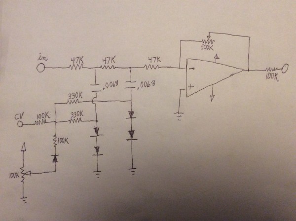
I have built multiple (maybe 13 in total!) Voltage Controlled Filters based on Tim Escobedo and G Meredith's version of the Q&D filter design for a bunch of different modified and circuit bent CASIO SKs. Anyway, I always find the range not quite what I want. What part(s) of the circuit should I look at to increase the frequency range - both how low the cut off goes, and how high the frequencies are that are let through at the upper extreme.
 |
|
|
Back to top
|
|
 |
blue hell
Site Admin

Joined: Apr 03, 2004
Posts: 24085
Location: The Netherlands, Enschede
Audio files: 278
G2 patch files: 320
|
| Posted: Wed Nov 02, 2016 10:56 am Post subject:
|
|
|
I'd try to lower the 100 k CV related resistors to get more range (but leave some resistance, say 10 k minimal). When it won't go low enough anymore after that you could make the 0.01 µF (or 0.02 µF, depending on version) filter caps larger. Not sure if it would work, but it is what I would try.
_________________
Jan
also .. could someone please turn down the thermostat a bit.
 |
|
|
Back to top
|
|
|
elektrouwe
Joined: May 27, 2012
Posts: 143
Location: Germany
|
| Posted: Sun Nov 06, 2016 2:25 am Post subject:
|
|
|
the LED is used as a voltage controlled "resistor" here.
the best range spreading of this "R_led" would be to drive it from a voltage source. Then R_led would change exponentially over many decades which is
what we want. BUT:
the CV series resistor of the LED drive is parallel to R_led for signals !
so reducing the 100k to small values will not help.
The solution is to replace the LED by 2 LEDs in series and connect the center of the LEDs to the center of the C's.
Now you can reduce the 100k CV-resistors to very small values and get
a wide almost expo. sweep range.
2 LEDs in series need a lot of CV. if you replace them by 1N4148 you can bring down CV |
|
|
Back to top
|
|
|
Cfish

Joined: Feb 24, 2016
Posts: 477
Location: Indiana
|
|
|
Back to top
|
|
|
elektrouwe
Joined: May 27, 2012
Posts: 143
Location: Germany
|
| Posted: Tue Nov 08, 2016 2:53 am Post subject:
|
|
|
| Cfish wrote: |
Have used this one too. For an easy filter it isn't too bad.
|
??? from interpreting the schematics, it can't sound too good :
- no resonance at all
- cut off frequency is fixed by 47k resistors and 6n8 caps
- CV is just "mixing in" a fixed cut off LP by slowly grounding the caps
I really would like to hear a sound demo, bcause I admit judging a filter just by schematics might not be a good idea  |
|
|
Back to top
|
|
|
Cfish
Joined: Feb 24, 2016
Posts: 477
Location: Indiana
|
| Posted: Thu Nov 10, 2016 6:05 pm Post subject:
|
|
|
Pretty much sounds like sweeping the tone knob on a guitar.
I however use it a lot. Usually with 3 octaves of square wave mixed, then sweep it with an inverted AD envelope signal. |
|
|
Back to top
|
|
|
elektrouwe
Joined: May 27, 2012
Posts: 143
Location: Germany
|
| Posted: Fri Nov 11, 2016 1:29 am Post subject:
|
|
|
| Cfish wrote: | Pretty much sounds like sweeping the tone knob on a guitar.
|
that's exactly what I've expected. For me it is not "moogish" enough to call it a VCLPF. I did a simulation meanwhile, also with some other simple filters, and will start a new thread about |
|
|
Back to top
|
|
|
Cfish
Joined: Feb 24, 2016
Posts: 477
Location: Indiana
|
| Posted: Fri Nov 11, 2016 2:22 pm Post subject:
|
|
|
| I think that's a great idea Elektrouwe. Can never have too many basic circuits to experiment with. Basic VCF schematics have not been as easy for me to find as some circuits are |
|
|
Back to top
|
|
|
sourcery
Joined: Feb 16, 2007
Posts: 11
Location: Sweden
|
Posted: Thu Feb 07, 2019 12:09 am Post subject:
 What a difference the two 1N4148 does instead of the LED! What a difference the two 1N4148 does instead of the LED! |
|
|
Just wanted to say thank you for the tip on the 2 1N4148 diodes! I built it all three ways (the two on the schematics and then the lower schematics with the 2 1N4148s instead) and the result went from "meh" to "wow"
Here is a video if you want to hear what it sounds like in the three different configurations: https://www.youtube.com/watch?v=fLR1B6JqyNA
Thanks for sharing this information, the video refers/links to this post for any viewer who is interested in the subject. |
|
|
Back to top
|
|
|
elektrouwe
Joined: May 27, 2012
Posts: 143
Location: Germany
|
| Posted: Thu Feb 07, 2019 3:04 am Post subject:
Re: What a difference the two 1N4148 does instead of the LED! |
|
|
| sourcery wrote: | | Just wanted to say thank you for the tip on the 2 1N4148 diodes! |
you are welcome! Your feedback is the first and only one - funny, how long it takes for a simple "1 diode" improvement idea to make it into real world designs. Thanks for sharing the idea on youtube - I like your " DIY Modular in a week" series on your channel ! |
|
|
Back to top
|
|
|
|

 Forum index » DIY Hardware and Software