| Author |
Message |
gasboss775

Joined: Jan 02, 2016
Posts: 217
Location: Scotland
|
 Posted: Thu May 04, 2017 12:55 am Post subject:
Augmentations for Casio MT65 Keyboard Posted: Thu May 04, 2017 12:55 am Post subject:
Augmentations for Casio MT65 Keyboard |
  |
|
I acquired a Casio MT65 "toy" keyboard as a result of my eldest daughter clearing out her room.
It's actually not bad for a toy. However I did think that it could be improved upon. So far the following circuits have only been breadboarded, but they do work.
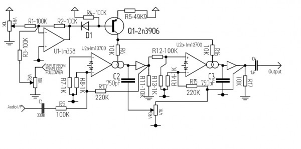
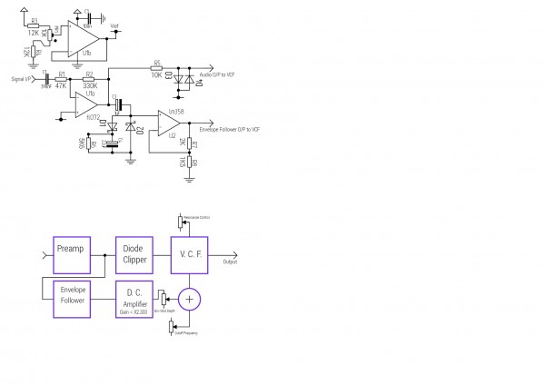
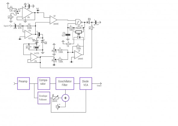
First up, Goschillator filter circuit. .
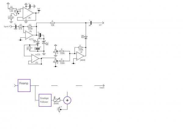
Modulated clipper circuit.
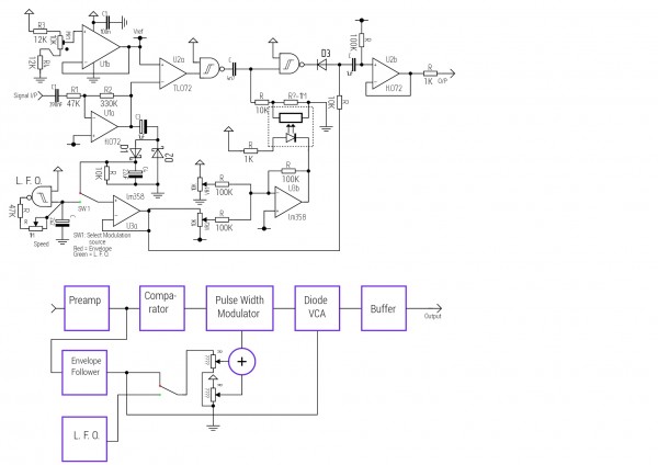
PWM circuit
| Description: |
|
| Filesize: |
243.25 KB |
| Viewed: |
674 Time(s) |
| This image has been reduced to fit the page. Click on it to enlarge. |
|
| Description: |
|
| Filesize: |
179.17 KB |
| Viewed: |
600 Time(s) |
| This image has been reduced to fit the page. Click on it to enlarge. |
|
| Description: |
|
| Filesize: |
313.56 KB |
| Viewed: |
647 Time(s) |
| This image has been reduced to fit the page. Click on it to enlarge. |
|
|
|
|
Back to top
|
|
 |
gasboss775
Joined: Jan 02, 2016
Posts: 217
Location: Scotland
|
|
|
Back to top
|
|
|
gasboss775
Joined: Jan 02, 2016
Posts: 217
Location: Scotland
|
|
|
Back to top
|
|
|
gasboss775
Joined: Jan 02, 2016
Posts: 217
Location: Scotland
|
|
|
Back to top
|
|
|
PHOBoS

Joined: Jan 14, 2010
Posts: 5818
Location: Moon Base
Audio files: 709
|
| Posted: Mon May 08, 2017 5:58 am Post subject:
|
|
|
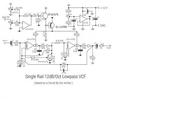
ah, the good old Eric Archer LPF. I still have one laying around here which I am thinking of putting in a box with some other circuits
I have. So this thread is inspirational  I build mine with a I build mine with a TL072 TLC2262CP and didn't encounter any problems, or at least it sounds great. I
also used an opamp for the fake GND.
Since you already have a squared up version of the signal you could put the CD4026 with an R2R in there as a suboscillator.
It would only take 1 chip and a couple of resistors (and a mixer I guess).
(in case you missed it I posted a track in which I used it here and the patch here)
_________________
"My perf, it's full of holes!"
http://phobos.000space.com/
SoundCloud BandCamp MixCloud Stickney Synthyards Captain Collider Twitch YouTube
Last edited by PHOBoS on Tue May 09, 2017 3:22 pm; edited 1 time in total |
|
|
Back to top
|
|
|
gasboss775
Joined: Jan 02, 2016
Posts: 217
Location: Scotland
|
|
|
Back to top
|
|
|
PHOBoS
Joined: Jan 14, 2010
Posts: 5818
Location: Moon Base
Audio files: 709
|
| Posted: Tue May 09, 2017 3:28 pm Post subject:
|
|
|
oops  I took a closer look at the opamp and I actually used a TLC2262CP. It had collected some dust over I took a closer look at the opamp and I actually used a TLC2262CP. It had collected some dust over
the time it has been laying around here and I only took a quick glance. Had no idea I actually used a rail-to-rail opamp.
what exactly do you mean by tracking pitch, something that isn't a squarewave ? I assume that by squaring up the signal you
pretty much have something that tracks pitch. A divider might clean it up a bit though. The 4046 can also be used as a pitch
tracker but it is mostly fun when it fails doing that correctly 
_________________
"My perf, it's full of holes!"
http://phobos.000space.com/
SoundCloud BandCamp MixCloud Stickney Synthyards Captain Collider Twitch YouTube |
|
|
Back to top
|
|
|
gasboss775
Joined: Jan 02, 2016
Posts: 217
Location: Scotland
|
| Posted: Tue May 09, 2017 3:38 pm Post subject:
|
|
|
| PHOBoS wrote: | oops I took a closer look at the opamp and I actually used a TLC2262CP. It had collected some dust over
the time it has been laying around here and I only took a quick glance. Had no idea I actually used a rail-to-rail opamp.
what exactly do you mean by tracking pitch, something that isn't a squarewave ? I assume that by squaring up the signal you
pretty much have something that tracks pitch. A divider might clean it up a bit though. The 4046 can also be used as a pitch
tracker but it is mostly fun when it fails doing that correctly |
I was thinking about something that could generate a control voltage, that in turn could be fed to several oscillators for the creation of a much bigger sound.
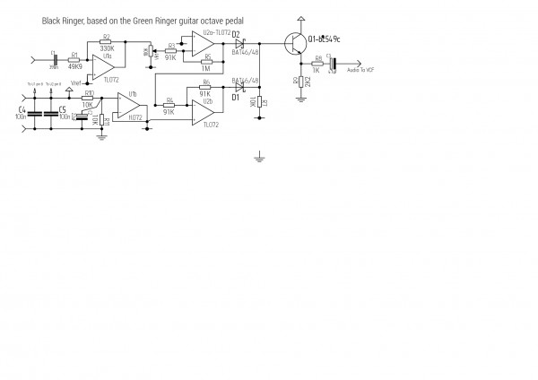
I do in fact have something in mind that might do the trick. It was a DIY guitar fx unit from a really old electronics mag ( 1987 I think ) the idea was for an oscillator to track the guitar then the output of the oscillator was combined with the guitar signal using a ring modulator. The title of the project was "
Light Metal Effects" anyway I was thinking of trying this to see how well it would track the Casio keyboard.
I had wondered about the 4046 too, didn't you post something like that before? |
|
|
Back to top
|
|
|
gasboss775
Joined: Jan 02, 2016
Posts: 217
Location: Scotland
|
| Posted: Mon Sep 17, 2018 9:34 am Post subject:
|
|
|
I have been doing some more experimenting with this interesting old instrument ( too good to be described as just a toy IMHO. )
I have added separate outs for the drums ( analogue ) and accompaniment parts to allow for separate processing of these parts, the original output is used for the keyboard part of the instrument.
I have tried a few circuits with interesting results though I haven't got around to draughting schematics for them yet, other than scribbled on paper!
I plan on posting my schematics here once they are done,
WATCH THIS SPACE ! |
|
|
Back to top
|
|
|
|

 Forum index » DIY Hardware and Software » Circuit Bending