| Author |
Message |
gasboss775

Joined: Jan 02, 2016
Posts: 217
Location: Scotland
|
 Posted: Wed May 10, 2017 12:00 pm Post subject: Posted: Wed May 10, 2017 12:00 pm Post subject:
 What Do You Think Is The Clock out on PT2399 is for? What Do You Think Is The Clock out on PT2399 is for? |
  |
|
No prizes for spotting the glaring grammatical error in the Title
I haven't seen a satisfactory explanation anywhere as to the purpose of the clock output on the PT2399 Echo/ Delay chip. One possible use that I considered is for driving switched capacitor filters that could adapt to varying delay times, as shorter delays could be permitted a wider bandwidth than with longer delay times. The Standard protocol is to use fixed frequency filtering at the input and output.
Any other thoughts about the clock pin, anyone?
Last edited by gasboss775 on Thu May 11, 2017 3:26 am; edited 1 time in total |
|
|
Back to top
|
|
 |
gasboss775
Joined: Jan 02, 2016
Posts: 217
Location: Scotland
|
| Posted: Thu May 11, 2017 3:24 am Post subject:
|
|
|
Someone on Muff Wiggler suggested using the clock output to measure the exact delay time. With a microprocessor ( microcontroller ) you could convert to milliseconds and drive a front panel display.
I was also thinking that you could sync an LFO or a sequencer to the pt2399 clock using dividers ( probably using 74HC counters as the clock is too fast for 4000B logic ) |
|
|
Back to top
|
|
|
PHOBoS

Joined: Jan 14, 2010
Posts: 5950
Location: Moon Base
Audio files: 709
|
|
|
Back to top
|
|
|
gasboss775
Joined: Jan 02, 2016
Posts: 217
Location: Scotland
|
| Posted: Thu May 11, 2017 1:17 pm Post subject:
|
|
|
| PHOBoS wrote: | I don't know what it originally is intended it is for but you can use it to make a tempo indicator.
Note that you absolutely need to use the 74HC(T) series for this as regular CMOS is too slow. |
Does the indicator flash 4 times at the BPM rate, assuming you're working in 4/4 time?
Also have you tried slaving a sequencer to the output of this circuit? |
|
|
Back to top
|
|
|
gasboss775
Joined: Jan 02, 2016
Posts: 217
Location: Scotland
|
| Posted: Thu May 11, 2017 1:33 pm Post subject:
|
|
|
Slightly off the original topic but still pt2399 related. The chip gets really freaky if you use large values for the timing resistor, such that the clock is slow. I'm planning on introducing modulation using a vactrol. As you get cool pitch bending effects with long delays.
I was thinking about chaining a few pt2399 as they're so cheap, but I think the noise and distortion could easily get out of hand. Perhaps a compander could keep things a bit cleaner?
Think I have an NE570 that I salvaged from an old digital delay. |
|
|
Back to top
|
|
|
AlanP
Joined: Mar 11, 2014
Posts: 746
Location: New Zealand
Audio files: 41
|
| Posted: Thu May 11, 2017 8:56 pm Post subject:
|
|
|
| Try using the LTC1063 -- you can run the clock out through a divider, and feed that into the filter chips. They work nicely with the PT2395. |
|
|
Back to top
|
|
|
PHOBoS
Joined: Jan 14, 2010
Posts: 5950
Location: Moon Base
Audio files: 709
|
| Posted: Fri May 12, 2017 1:22 am Post subject:
|
|
|
| gasboss775 wrote: | Does the indicator flash 4 times at the BPM rate, assuming you're working in 4/4 time?
Also have you tried slaving a sequencer to the output of this circuit? |
It's been a while since I used it but I think it flashes with the delay tempo so BPM x1. A quick guess is that if you
want it to be 4x as fast you can leave out the diode connected to pin 14 of the second divider and take the output
from pin 13. I never used it as a CLK source to control something else but that should work.
_________________
"My perf, it's full of holes!"
http://phobos.000space.com/
SoundCloud BandCamp MixCloud Stickney Synthyards Captain Collider Twitch YouTube |
|
|
Back to top
|
|
|
gasboss775
Joined: Jan 02, 2016
Posts: 217
Location: Scotland
|
| Posted: Fri May 12, 2017 10:52 am Post subject:
|
|
|
Turns out that using a vactrol to control the pt2399 delay time doesn't work that well ( it is very uneven ) Anyway I used a current sink and that worked a lot better, though I was struggling to get really short delay times for chorus type effects, though I did manage to get a fairly good chorus, albeit with a bit of perceptible delay. I've seen some online circuits that modulate the delay time using the Vref pin, that seems a bit of an odd way of doing things but I might give it a try.
I will do a quick schematic of my current sink circuit. |
|
|
Back to top
|
|
|
gasboss775
Joined: Jan 02, 2016
Posts: 217
Location: Scotland
|
|
|
Back to top
|
|
|
PHOBoS
Joined: Jan 14, 2010
Posts: 5950
Location: Moon Base
Audio files: 709
|
|
|
Back to top
|
|
|
gasboss775
Joined: Jan 02, 2016
Posts: 217
Location: Scotland
|
|
|
Back to top
|
|
|
LFLab
Joined: Dec 17, 2009
Posts: 497
Location: Rosmalen, Netherlands
|
| Posted: Sun May 14, 2017 2:14 pm Post subject:
|
|
|
| AlanP wrote: | | Try using the LTC1063 -- you can run the clock out through a divider, and feed that into the filter chips. They work nicely with the PT2395. |
See Blacet Time Machine, I do wonder about the long term availability of LTC1063, they do have in SMT, but the IC's are not too common, and it seems to be quite a specialty IC. |
|
|
Back to top
|
|
|
L´Andratté

Joined: Sep 23, 2012
Posts: 153
Location: Hamburg, Germany
Audio files: 5
|
| Posted: Wed May 17, 2017 10:36 am Post subject:
|
|
|
Have you seen how the voltage control is realized in Rob Hordijk´s Zeitgeist?
It´s on his subforum here.
I have built it, it works very well. Couldn´t get simpler, a total hack, beautiful!
I cannot understand, why it seems to be totally ignored by everyone...  |
|
|
Back to top
|
|
|
gasboss775
Joined: Jan 02, 2016
Posts: 217
Location: Scotland
|
| Posted: Thu May 18, 2017 5:37 am Post subject:
|
|
|
| L´Andratté wrote: | Have you seen how the voltage control is realized in Rob Hordijk´s Zeitgeist?
It´s on his subforum here.
I have built it, it works very well. Couldn´t get simpler, a total hack, beautiful!
I cannot understand, why it seems to be totally ignored by everyone... |
I found a schematic for it on THIS Thread, but I'm confused as it does nor specify what is connected to j2?
The most obvious interpretation is that its a switch or it could be a switched jack.
EDIT: I just found a picture of a completed PCB of the Zeitgeist and it is just a jumper!
Last edited by gasboss775 on Thu May 18, 2017 5:52 am; edited 1 time in total |
|
|
Back to top
|
|
|
L´Andratté
Joined: Sep 23, 2012
Posts: 153
Location: Hamburg, Germany
Audio files: 5
|
| Posted: Thu May 18, 2017 5:47 am Post subject:
|
|
|
Pin 6 is basically connected to a voltage potential (depending up to nearly +5V/0V), where the 0V side can be switched between modulation with CV or with an LDR.
Now I understand there should be current drawn out of pin 6 which has a fixed voltage, but this works just beautifully over the whole delay range of the PT.
It´s drawn a bit confusing, granted... |
|
|
Back to top
|
|
|
gasboss775
Joined: Jan 02, 2016
Posts: 217
Location: Scotland
|
| Posted: Thu May 18, 2017 5:57 am Post subject:
|
|
|
| L´Andratté wrote: | Pin 6 is basically connected to a voltage potential (depending up to nearly +5V/0V), where the 0V side can be switched between modulation with CV or with an LDR.
Now I understand there should be current drawn out of pin 6 which has a fixed voltage, but this works just beautifully over the whole delay range of the PT.
It´s drawn a bit confusing, granted... |
What was the sensor that is connected to HDR_10? Is it an LDR?
DOH! I just reread your post and you did mention that it's an LDR! |
|
|
Back to top
|
|
|
gasboss775
Joined: Jan 02, 2016
Posts: 217
Location: Scotland
|
| Posted: Thu May 18, 2017 6:02 am Post subject:
|
|
|
Have you any idea what the voltage range of the CV was, is it 0 to +10V ?
Looks like it would work with 0 to +10 V CV. I do agree that it is brilliantly simplistic! |
|
|
Back to top
|
|
|
L´Andratté
Joined: Sep 23, 2012
Posts: 153
Location: Hamburg, Germany
Audio files: 5
|
| Posted: Thu May 18, 2017 6:13 am Post subject:
|
|
|
Ah some time ago. IIRC JP2 switches the bottom leg of the delay pot between ground/sensor off or var. resistor to ground/sensor on. The sensor could be a LDR or pressure pad or ribbon element.
I have used two of the Zeitgeist in a setup with two Benjolins very often and it had no problem with the benjolin oscillators as CV, they have voiltage range from at least +/-4V I think. Since the voltage of pin 6 stays the same only current draw changes, that seems to be ok, worst thing that happend was latch-up (it happens with the 2399, just switch quickly off and on again).
I must say with the filtering and all this circuit, while defintly not high end, has a nice sound to it which makes it very recognizable. |
|
|
Back to top
|
|
|
gasboss775
Joined: Jan 02, 2016
Posts: 217
Location: Scotland
|
| Posted: Thu May 18, 2017 7:24 am Post subject:
|
|
|
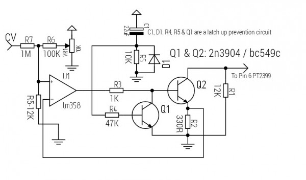
| The PT2399 latchup problem can be avoided by ensuring that the load on pin6 doesn't go below 4K7 within the first 400 milliseconds after power up. There are various ways to go about this. I suspect it might be a bad idea to let pin 6 go below ground. For the Zeitgeist setup I'd suggest the CV should be in the 0 to + 5V range to be on the safe side. |
|
|
Back to top
|
|
|
gasboss775
Joined: Jan 02, 2016
Posts: 217
Location: Scotland
|
| Posted: Fri Jun 02, 2017 2:19 pm Post subject:
|
|
|
| PHOBoS wrote: | For what it's worth here is the section of the Moon Base Xplorer that has the PT2399 delay.
 |
PHOBoS are you sure that you used a PNP transistor to control the delay time? Would seem more apt to use an NPN there? |
|
|
Back to top
|
|
|
gasboss775
Joined: Jan 02, 2016
Posts: 217
Location: Scotland
|
| Posted: Sat Jun 03, 2017 8:49 am Post subject:
|
|
|
| Has anyone here used a compander ( ne570/1/2,etc ) with a pt2399 delay circuit? If so did it provide a worthwhile improvement in its performance? |
|
|
Back to top
|
|
|
PHOBoS
Joined: Jan 14, 2010
Posts: 5950
Location: Moon Base
Audio files: 709
|
|
|
Back to top
|
|
|
Dave Kendall

Joined: May 26, 2007
Posts: 421
Location: England
Audio files: 3
|
| Posted: Sun Jun 04, 2017 4:01 pm Post subject:
|
|
|
A thought - depending on how it behaves, possibly CLK out on the PT2399 could be used for linking another PT2399, giving stereo or ping-pong delays.
_________________
"Everything in moderation, including moderation" |
|
|
Back to top
|
|
|
AlanP
Joined: Mar 11, 2014
Posts: 746
Location: New Zealand
Audio files: 41
|
| Posted: Sun Jun 04, 2017 4:12 pm Post subject:
|
|
|
The PT2399 does not have a clock in. PT2395 does, but not the '99.
With the pedal applications I've seen, multiple PT2399s or modulation, typically use current mirrors, IIRC. |
|
|
Back to top
|
|
|
Dave Kendall
Joined: May 26, 2007
Posts: 421
Location: England
Audio files: 3
|
| Posted: Sun Jun 04, 2017 4:14 pm Post subject:
|
|
|
oops - my bad. . . thinking of the wrong chip. Doh!
_________________
"Everything in moderation, including moderation" |
|
|
Back to top
|
|
|
|

 Forum index » DIY Hardware and Software