| Author |
Message |
Dr. G.
Joined: Dec 06, 2017
Posts: 6
Location: Luxembourg
|
 Posted: Wed Dec 06, 2017 12:41 am Post subject:
Debugging Noise Toaster Posted: Wed Dec 06, 2017 12:41 am Post subject:
Debugging Noise Toaster |
  |
|
Hi,
The wierd sound generator was easy to build, so I thought I'd step up to the noise toaster. Completed the build, but no toast. I'm looking for some help debugging it.
My multimeter suggests a possible culprit: the circuit's main virtual ground is off.
The ground is set by resistors 37 & 42, both 4.7K. However, my measured resistance from BP to Ground is ~1K, while from BN to ground is ~2K. As would be expected, I'm thus observing BP as 1.7V above ground, while BN is 5.3V below ground; Likewise, a number of other values as measured at the inputs to the various op-amps agree with what the book indicates they should be, except shifted by the 2:1 ratio caused by the fault in the virtual ground (this is good news, it suggests that most things are right if I can fix the ground). For example, the wiper on variable resistor R1, which controls the frequency of the VCO, should vary from -4.5V to +4.5V (to ground). On my unit, it runs from -6.57V to +1.8V.
Could someone with a working unit share what they measure for resistance and current BP-Ground and BN-Ground (so I know what the correct values are?).
I'd also love any specific suggestions as to what part(s) of the circuit are worth extra close scrutiny.
Since I expect BP-Ground resistance near 2K (hoping to check this by comparison to a working circuit, hence my post here) and observe a measured resistance of half that, I suspect a short someplace (is this reasonable? Any other ideas as to possible causes?)
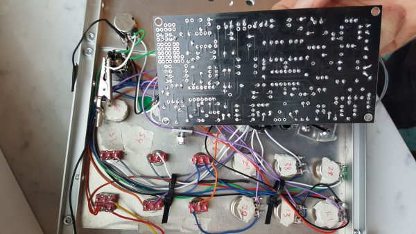
This is almost certainly a "poor assembly" error. I built it from the Soundtronics kit. I worked very slowly through the build, checking each component 3 times prior to install. Likewise with the panel wiring, every wire was labeled prior to soldering and triple-checked vs the schematics. What I'm saying is all components and wiring should be correctly placed (not well installed, but at least in the correct place). You'll see from the photo that I'm not that good with a soldering iron...
| Description: |
| The underside of the unit and panel |
|
| Filesize: |
1.41 MB |
| Viewed: |
618 Time(s) |
| This image has been reduced to fit the page. Click on it to enlarge. |
|
|
|
|
Back to top
|
|
 |
Sven
Joined: Mar 10, 2017
Posts: 53
Location: Norway
|
| Posted: Mon Jan 01, 2018 8:50 am Post subject:
|
|
|
Hello,
I havent build the Noise Toaster yet so cant help with measurements. Sorry, but your soldering looks bad. Are you using leadfree solder? My first guess is a problem with one or more solderjoints. My suggestion to you is to go over all of the solderjoints and correct them. Watch some Youtube videos about soldering, i think this one is very helpful https://www.youtube.com/watch?v=AqvHogekDI4 .
Good luck Sven |
|
|
Back to top
|
|
|
Dr. G.
Joined: Dec 06, 2017
Posts: 6
Location: Luxembourg
|
| Posted: Mon Jan 01, 2018 10:06 am Post subject:
resoldering |
|
|
Hi, Sven,
Thanks for the reply. Yes, it is lead-free solder, yes it was a bad job. I've gone over all of the solder joins since then and reflowed them; I also clipped back the excess wires.
The board now looks much better, but the basic problem hasn't changed. I'm not saying bad soldering wouldn't have caused other problems, but it doesn't seem to be behind this one.
Also, I've gone over the wiring multiple times. Each time, everything checks out.
really puzzled about what it could be, also frustrated. |
|
|
Back to top
|
|
|
Dr. G.
Joined: Dec 06, 2017
Posts: 6
Location: Luxembourg
|
| Posted: Sun Jan 07, 2018 3:31 am Post subject:
Some progress |
|
|
I found one cause of the faulty ground. I was using the kludge area to add a stereo mixer. However, one of the kludge terminals connects to C22 (as per the board wiring diagram), and guess which one I was using? I've moved the mixer over to a different spot.
I'm now measuring voltage BP to ground of 4.48V and voltage BN to ground of -4.13V (measured at the terminals of pot R1 to the baseplate), a difference of ~0.35V. This is close enough for everything except the VCO to work. I can make white noise sounds, modify them with the filter, and modulate the filter with the LFO/AR. Also, my stereo pot works 
But the VCO is not oscillating.
The VCO has its own virtual ground, labeled G2, made by the R22/R23 voltage divider buffered with capacitors C4 and C5. G2 very well balanced in my case, with resistance G2 => BP and G2 => BN both 2.84K Ohms, and a clean +/- 4.29 V difference to BP/BN. This virtual ground connects to U1 pins 3, 10, and 12, also to Q4's base. I measure zero resistance between each of these points. Likewise, when powered on, each of the above points shows identical voltage.
However, the measured voltage at G2 is 0.172 V above circuit ground. Thus the VCO's ramp generator (U1-A) sees 0.172 V at its non-inverting input (pin 3) vs 0.137V at its inverting input (pin 2), and its output (pin 1) is a steady -2.64V (all voltage measured to main ground by placing the probe on the aluminum baseplate). |
|
|
Back to top
|
|
|
|

 Forum index » DIY Hardware and Software » MusicFromOuterSpace.com designs by Ray Wilson
