| Author |
Message |
dk
Joined: Feb 12, 2019
Posts: 115
Location: Europe
|
 Posted: Sun Oct 06, 2019 3:01 am Post subject:
555 AD/AR issues Posted: Sun Oct 06, 2019 3:01 am Post subject:
555 AD/AR issues |
  |
|
Hi all,
I have one of PHOBoS's 555-based AD/AR on breadboard, but 2 things are happening with it that I don't 100% understand:
- The attack knob influences the maximum voltage the envelope generator can put out, and;
- I expected the threshold to be around 2/3rds of the supply voltage (9V in my case), but when the attack knob is fully fast, the output consistently hits 8.54V.
The range of output on the attack knob varies between a bit over 6V on the slow end and makes it's way up fairly linearly to that 8.54V on the fast end. Is this normal behavior for this type of circuit? Assuming it won't hurt anything, the high output isn't a big deal, as I'm using a voltage divider on the output anyway... the overall output thing is a bit weird, though certainly not world ending (it's a feature?  ) )
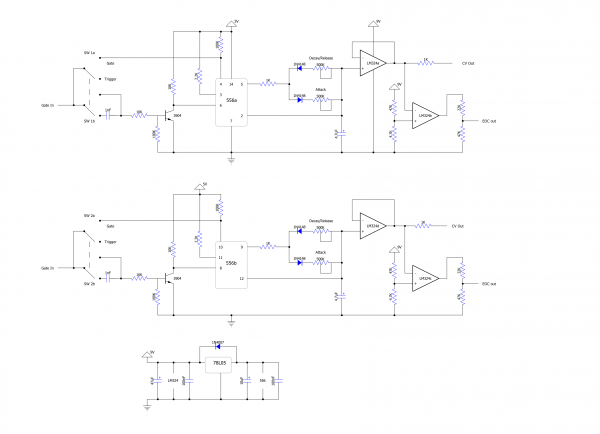
I'll just note that while testing, I'm using a CMOS 556 with the unused side having its reset pin tied to ground.
Here's PHOBoS's circuit re-drawn. The only thing I didn't have on hand was a 10n capacitor for the CV control, but I've tried values above and below it, as well as tying it directly to ground and it hasn't effected anything. I've been taking the measurements mentioned above at the leg of the 100k resistor attached to the timing capacitor and attack & release pots.
| Description: |
|
| Filesize: |
172.36 KB |
| Viewed: |
680 Time(s) |
| This image has been reduced to fit the page. Click on it to enlarge. |
|
|
|
|
Back to top
|
|
 |
PHOBoS

Joined: Jan 14, 2010
Posts: 5947
Location: Moon Base
Audio files: 709
|
| Posted: Sun Oct 06, 2019 5:33 am Post subject:
Re: 555 AD/AR issues |
|
|
I haven't used it with a 556 but that shouldn't make any difference. Also this version works the same with either the regular
or CMOS version so that shouldn't cause any problems either.
| Quote: | | - The attack knob influences the maximum voltage the envelope generator can put out |
This sounds like the impedance of the output transistor is influencing it. If you think of it as a resistor it will form a voltage divider
with the attack pot. So the higher the value of the attack pot (slower attack) the lower the ouput voltage will be, which is the behaviour
you describe. Since you have it on breadboard you could test this by leaving out the transistor stage and measure the voltage over the
capacitor to see if the voltage still changes depending on the attack pot setting. Because the value of this pot is fairly high it is possible
that the meter might cause a very slight variation in the voltage but it shouldnt be much.
| Quote: | | - I expected the threshold to be around 2/3rds of the supply voltage (9V in my case), but when the attack knob is fully fast, the output consistently hits 8.54V. |
Does this happen in both AD and AR mode ? In AR mode this is expected behaviour but in AD mode it should indeed be 2/3 of the supply voltage.
This image (from the most excellent, highly recommened 555 tutorials) showing the 555 internals is very useful in understanding why.

ignore the external components as the 555 is not used in astable mode for the envelope generator
Assume that at the start the timing capacitor (the one connected to the treshold input) is dicharged. When the 555 receives a voltage lower
than 1/3Vcc (set by the lower comparator) on the trigger input the internal Flip Flop wil be SET. As a result the output goes high and it charges
the capacitor. In AD mode the trigger input only receives a short pulse so once the capacitor is charged up to the treshold level of 2/3Vcc (set by
the upper comparator) the internal Flip Flop is RESET which causes the output to go low and discharge the capacitor. (Attack, Decay)
In AR mode it's a bit different. If the voltage over the capacitor reaches 2/3Vcc but the trigger input is still <1/3Vcc the internal Flip Flop stays
SET. Since the ouput of the NE555 is almost Vcc the capacitor gets charged further up to this voltage (minus a voltage drop because of the diode).
Only when the trigger input goes above 1/3Vcc will the Flip Flop be RESET again and the capacitor dicharged. Note that in AR mode the Flip Flop
will also be RESET (through the reset pin) when the input goes low even if the voltage hasn't reached 2/3Vcc yet. (Attack, Release)
I had noticed this behaviour before and made a different version which I used in the Moon Base Xplorer
| Quote: | With a +12V supply the 555 will only charge the capacitor to about 8V (2/3 x Vdd) before it discharges it (in AD mode). But I wanted 10V,
which I could have done with the opamps, instead I just raised the treshold level by adding a pullup resistor to the CV input (pin 5). To make
sure the voltage doesn't rise above 10V (in AR mode) I added a zenerdiode.
The levels (treshold/limit) are very close together, I've build 2 of these and while 1 worked with a 47K pullup resistor the other one still didn't
work with a 51K resistor. (solved it by adding a 1M pulldownn resistor aswell). So it would probably be wise to use a trimpot instead. |
note that these resistor values are for the CMOS version, for the regular version they will have to be much lower.
btw, the LEDs seem to be drawn reversed in your schematic.
_________________
"My perf, it's full of holes!"
http://phobos.000space.com/
SoundCloud BandCamp MixCloud Stickney Synthyards Captain Collider Twitch YouTube
Last edited by PHOBoS on Sun Oct 06, 2019 6:38 am; edited 1 time in total |
|
|
Back to top
|
|
|
dk
Joined: Feb 12, 2019
Posts: 115
Location: Europe
|
| Posted: Sun Oct 06, 2019 6:18 am Post subject:
|
|
|
I'll report back in once I can sit down at the breadboard, but I think you've probably nailed it.
I don't have an oscilloscope, so I've been using a standard multimeter to measure the output. Since it's not fast enough to catch the peak in AD mode, I've only been measuring in AR mode... I guess that explains the high output! I did try using a zener as you did in your Moon Base Explorer, but it dropped the voltage significantly below the target. Perhaps, though, that was a side effect of what you described with the transistor.
As for the attack controlling the output, I did in fact measure without the transistor in, but I think I had something funky going on with that particular row on the breadboard (ie it was being shorted to the row next to it with the voltage divider)... I have it moved to the other side of the breadboard now anyway, so I'll double check it once I get home.
Thanks for posting that info about the 555... it completely makes sense now.
I was thinking of dropping the output transistors in favor of a voltage follower as in the circuit your just posted, thinking I could use the leftover parts of a lm324 to either make invertors as you did, or as a comparator on the output to use for re-triggering. Assuming dropping the transistor fixes the problem, I guess that's the way to go.
A quick question... it's safe to assume that the zener has to be at or above the threshold voltage, otherwise the AD mode wouldn't function correctly, right?
(and yes, I drew my LEDS backwards... sorry! ) |
|
|
Back to top
|
|
|
PHOBoS
Joined: Jan 14, 2010
Posts: 5947
Location: Moon Base
Audio files: 709
|
| Posted: Sun Oct 06, 2019 6:34 am Post subject:
|
|
|
| dk wrote: | | Thanks for posting that info about the 555... it completely makes sense now. |
excellent! It's fairly simple circuit once you understand how it works.
| Quote: | | A quick question... it's safe to assume that the zener has to be at or above the threshold voltage, otherwise the AD mode wouldn't function correctly, right? |
yes, that is correct. This is also what was causing the problem on AD/AR #2 for which I had to use a different resistor value connected
to the CV input. With the 47K the treshold voltage was set higher than the maximum voltage it could reach because of the zenerdiode.
I was thinking if you want a 5V output you could use a 5V1 zener diode and adjust the treshold level to be just below that by connecting
a resistor between the CV input and GND. No idea what the value would be so you'll have to experiment. This way you don't need an extra
voltage divider on the ouput.
_________________
"My perf, it's full of holes!"
http://phobos.000space.com/
SoundCloud BandCamp MixCloud Stickney Synthyards Captain Collider Twitch YouTube |
|
|
Back to top
|
|
|
dk
Joined: Feb 12, 2019
Posts: 115
Location: Europe
|
| Posted: Sun Oct 06, 2019 7:16 am Post subject:
|
|
|
| Quote: | | excellent! Very Happy It's fairly simple circuit once you understand how it works. |
I had gotten most of it, but it's always a missed detail that messes everything up, right?
| Quote: | I was thinking if you want a 5V output you could use a 5V1 zener diode and adjust the treshold level to be just below that by connecting
a resistor between the CV input and GND. No idea what the value would be so you'll have to experiment. This way you don't need an extra
voltage divider on the ouput. |
Good idea! I'll stick a trimmer there for now to dial it in. In your post with the Moon Base Explorer, you mentioned that you also needed a 1M resistor to ground in addition to the 51K you had going to VCC. Safe to say I'll need to have a (1M) resistor to VCC for it to work properly? |
|
|
Back to top
|
|
|
PHOBoS
Joined: Jan 14, 2010
Posts: 5947
Location: Moon Base
Audio files: 709
|
| Posted: Sun Oct 06, 2019 7:38 am Post subject:
|
|
|
| Quote: | | Good idea! I'll stick a trimmer there for now to dial it in. In your post with the Moon Base Explorer, you mentioned that you also needed a 1M resistor to ground in addition to the 51K you had going to VCC. Safe to say I'll need to have a (1M) resistor to VCC for it to work properly? |
1M shouldn't be needed. In my case the voltage was still just a bit too high with the 51K resistor and with 56K it was lower than I wanted, so the
1M pulls it down just a little bit. With a trimpot you can set it exactly right.
_________________
"My perf, it's full of holes!"
http://phobos.000space.com/
SoundCloud BandCamp MixCloud Stickney Synthyards Captain Collider Twitch YouTube |
|
|
Back to top
|
|
|
dk
Joined: Feb 12, 2019
Posts: 115
Location: Europe
|
| Posted: Mon Oct 07, 2019 12:44 am Post subject:
|
|
|
Ok, so I haven't gotten a chance to test using the LM324 in place of the transistor, but I did remove the transistor and measured.
- The transistor was in fact creating a voltage divider. The difference between full fast and full slow attack is now 0.1V, which is acceptable. I think I may now be able to use a bigger pot (500K) as well, which didn't work before, as it dropped the level below the upper threshold of the 556 in AD mode.
- Using the zener diode causes the problem to return. In addition to limiting the voltage, it's also functioning as a resistance to ground, so I'm afraid I'll have to ditch it.
What's next: Since the LM324 doesn't like input signals within 1.5V of VCC, I can't just slap it on the tail end of the circuit as-is (the 556 is now putting out 8.9V in AR mode). I'm thinking, though, that without the voltage divider transistor thing going on now, I may be able to go back to using the 556 at 5V, in which case I can just use your circuit from the Moon Base Explorer (adjusting the CV resistor, of course), and run just the LM324 off 9V to avoid that upper voltage limit. I'll also be able to ditch the 40106 which I only needed since I was trying to get a clean 9V pulse out of a 5V gate. That'll make the input section a bit simpler, keep the size of the vero down (it was going to be just a hair bigger then the panel I had intended to put it on), and perhaps I'll manage to squeeze in that comparator on the output (with a voltage divider, but hey, no free lunch) |
|
|
Back to top
|
|
|
dk
Joined: Feb 12, 2019
Posts: 115
Location: Europe
|
| Posted: Mon Oct 07, 2019 12:46 am Post subject:
|
|
|
| btw PHOBoS, was there any specific reason why you opted for 500K pots and a 4.7u/10u timing cap? A lot of designs floating around seem to use smaller caps + bigger pots... |
|
|
Back to top
|
|
|
PHOBoS
Joined: Jan 14, 2010
Posts: 5947
Location: Moon Base
Audio files: 709
|
| Posted: Wed Oct 09, 2019 10:47 am Post subject:
|
|
|
No particular reason that I recall, although it could be that the largest pots I had or could get at the time where 470K/500K.
1M will give you a larger range but with less accuracy, though I don't think that really matters for a circuit like this.
| Quote: | | - Using the zener diode causes the problem to return. In addition to limiting the voltage, it's also functioning as a resistance to ground, so I'm afraid I'll have to ditch it. |
when I looked up the schematic it actually made me question how well it works because zenerdiodes do require some current
to properly function. Also power rating can make a difference, I probably used 0.5W types. Maybe I'll just breadboard it too
and do some tests myself to see what happens.
_________________
"My perf, it's full of holes!"
http://phobos.000space.com/
SoundCloud BandCamp MixCloud Stickney Synthyards Captain Collider Twitch YouTube |
|
|
Back to top
|
|
|
dk
Joined: Feb 12, 2019
Posts: 115
Location: Europe
|
|
|
Back to top
|
|
|
Grumble

Joined: Nov 23, 2015
Posts: 1320
Location: Netherlands
Audio files: 30
|
| Posted: Fri Oct 18, 2019 12:54 pm Post subject:
|
|
|
I would place the input of the comparator directly over the 4.7uF caps so there is no interference caused by the following circuit plus the input offset currents of the two opamps may cancel out eachother.
_________________
my synth |
|
|
Back to top
|
|
|
dk
Joined: Feb 12, 2019
Posts: 115
Location: Europe
|
| Posted: Fri Nov 08, 2019 6:53 am Post subject:
|
|
|
Hi Grumble, thanks for your input! Sorry it took so long to post a reply... I couldn't work on my stuff for a bit, so I couldn't get back here with anything to report.
I decided to toss everything onto vero, hooking up that last comparator as you said (off the timing cap + attack/release knobs). Everything works wonderfully, EXCEPT (had to be something!):
When I plug the end of cycle (comparator) output back into the input in trigger mode, I can re-trigger the 556 and use it as an LFO... up until I turn the release knob more than halfway, when it suddenly decides it doesn't want to trigger anymore. I've checked:
- The comparator does actually go high when the cycle ends. (measures 4.7V)
- Hooking the comparator after the voltage follower doesn't change anything.
- Hooking the output of the comparator to other modules generally works as long as the release is not turned to high... when it is, things start acting funky, ie. the first division on my divider doesn't want to light up, first output of my 4015 doesn't light up, etc., while clocking off the comparator.
Do you guys have any idea what could be causing this? Lack of current off the voltage divider? Dirty output (I don't have a scope)? |
|
|
Back to top
|
|
|
|

 Forum index » DIY Hardware and Software » Lunettas - circuits inspired by Stanley Lunetta