| Author |
Message |
wax+wire
Joined: Sep 28, 2014
Posts: 17
Location: Australia
|
 Posted: Thu Jan 23, 2020 9:38 pm Post subject:
Passive Mixer for keyboard and drum channels - Casio SK5 Posted: Thu Jan 23, 2020 9:38 pm Post subject:
Passive Mixer for keyboard and drum channels - Casio SK5 |
  |
|
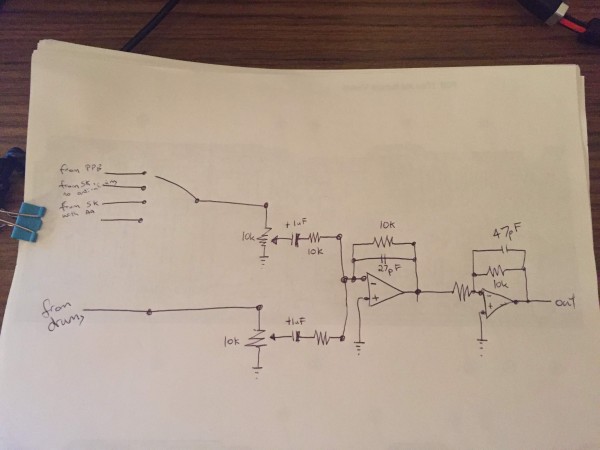
I've heavily bent my casio SK5 (and 8 and 1) and they have a drum channel and 4 voice channels. Those four voice channels I run through a basic VCF filter (or not, depending on what I want).
The issue is when summing the two channels together. I want seperate volume controls on them!
My circuit is basically this:

but the result is that when the drums channel is getting close to full volume (so say 500-0ohms resistance) it negatively affects the keyboard volume (i.e. makes the keyboard quieter).
Happy to make a simple op-amp mixer if that will solve the problem, but I can't workout why it doesn't work.
Thanks |
|
|
Back to top
|
|
 |
JovianPyx

Joined: Nov 20, 2007
Posts: 1988
Location: West Red Spot, Jupiter
Audio files: 224
|
| Posted: Fri Jan 24, 2020 7:03 am Post subject:
|
|
|
This is precisely why passive mixers are not recommended for audio. They are inexpensive and kinda work, but this is the kind of thing that happens and there's no way to fix it, it does what it does because of the laws of physics.
Find an active mixer schematic (an active mixer is a mixer that uses an op amp), there has to be hundreds of them on the internet.
The active mixer will fix this.
_________________
FPGA, dsPIC and Fatman Synth Stuff
Time flies like a banana.
Fruit flies when you're having fun.
BTW, Do these genes make my ass look fat?
corruptio optimi pessima
|
|
|
Back to top
|
|
|
PHOBoS

Joined: Jan 14, 2010
Posts: 5854
Location: Moon Base
Audio files: 709
|
| Posted: Fri Jan 24, 2020 9:10 am Post subject:
|
|
|
Hard to say why exactly it doesn't work without knowing more about the signals themselves and using an oscilloscope to see what happens.
Since the CASIO SK keyboards run on single supply you could try adding some capacitors between the channel outputs and the level pots to
block any DC voltage which might be causing some issues. It's hard to say though and yeah an active mixer will most likely solve it but
it's always worth trying a passive mixer first.
_________________
"My perf, it's full of holes!"
http://phobos.000space.com/
SoundCloud BandCamp MixCloud Stickney Synthyards Captain Collider Twitch YouTube |
|
|
Back to top
|
|
|
JovianPyx
Joined: Nov 20, 2007
Posts: 1988
Location: West Red Spot, Jupiter
Audio files: 224
|
| Posted: Fri Jan 24, 2020 9:56 am Post subject:
|
|
|
DC blocking caps would help to eliminate any DC bias, but won't do much to reduce the interaction. Raising the the 10K pots to 100K might help some.
There are several issues at work here, this circuit is similar to directly connecting outputs together. This causes distortion. Putting resistors in series with the signals helps, but doesn't eliminate the distortion. Bigger resistors reduce the effects, but they cause problems too - bigger resistors generate more noise which gets into your signal. None of these things happens with an active mixer.
Another problem is that synth electronics has an expansion creep factor. If you build a 2 input mixer, how long before you want a third or a fourth input? Not long in the majority of cases. Adding inputs to a passive mixer will just compound the problems already noted. However, the active mixer will accept as many inputs as you want without degrading the performance of the mixer.
Check the cost of an op amp. They really are not expensive and almost any of them will do.
_________________
FPGA, dsPIC and Fatman Synth Stuff
Time flies like a banana.
Fruit flies when you're having fun.
BTW, Do these genes make my ass look fat?
corruptio optimi pessima
|
|
|
Back to top
|
|
|
PHOBoS
Joined: Jan 14, 2010
Posts: 5854
Location: Moon Base
Audio files: 709
|
| Posted: Fri Jan 24, 2020 10:50 am Post subject:
|
|
|
Actually DC wouldn't cause the problem I was thinking about as it is a passive system so the voltage wouldn't accumulate as it
can with an active mixer. Adding capacitors might still do something though.
| Quote: | | when the drums channel is getting close to full volume (so say 500-0ohms resistance) it negatively affects the keyboard volume (i.e. makes the keyboard quieter). |
I do wonder what causes this though. Are the levels the same otherwise or is the drum channel already louder to start with ?
The output circuitry of the channels also matters. Ideally you want them to have a low impedance expecially with a passive mixer.
Something to keep in mind though is that even if it (passive mixer) would work you'd probably still need to buffer the output.
If you do this with an opamp you might aswell mix the signals with it too.
_________________
"My perf, it's full of holes!"
http://phobos.000space.com/
SoundCloud BandCamp MixCloud Stickney Synthyards Captain Collider Twitch YouTube |
|
|
Back to top
|
|
|
JovianPyx
Joined: Nov 20, 2007
Posts: 1988
Location: West Red Spot, Jupiter
Audio files: 224
|
| Posted: Fri Jan 24, 2020 10:59 am Post subject:
|
|
|
| PHOBoS wrote: | | I do wonder what causes this though. |
Looking at the schematic, see what happens when one of the pots is turned to ground. That pot grounds one end of the 10K resistor. This now forms a 1/2 voltage divider. The effect of this is more pronounced as the wiper approaches zero.
An active mixer will not do this.
_________________
FPGA, dsPIC and Fatman Synth Stuff
Time flies like a banana.
Fruit flies when you're having fun.
BTW, Do these genes make my ass look fat?
corruptio optimi pessima
|
|
|
Back to top
|
|
|
PHOBoS
Joined: Jan 14, 2010
Posts: 5854
Location: Moon Base
Audio files: 709
|
|
|
Back to top
|
|
|
JovianPyx
Joined: Nov 20, 2007
Posts: 1988
Location: West Red Spot, Jupiter
Audio files: 224
|
| Posted: Fri Jan 24, 2020 11:20 am Post subject:
|
|
|
Yes, it does both and turning the wiper all the way up also contributes more modulation distortion, so neither case is good.
Reading more about passive mixers, I see that some are built without pots. That would reduce some of the perceived problems (even though they are still present). They list yet more problems than we mention here, but the big one is interaction between the inputs. One person points out that if you made a passive mixer with say 9 inputs, each of the inputs would have a contribution of only 1/10 of it's full signal value. That means more gain is necessary to get an acceptable signal level and more gain means more noise.
_________________
FPGA, dsPIC and Fatman Synth Stuff
Time flies like a banana.
Fruit flies when you're having fun.
BTW, Do these genes make my ass look fat?
corruptio optimi pessima
|
|
|
Back to top
|
|
|
PHOBoS
Joined: Jan 14, 2010
Posts: 5854
Location: Moon Base
Audio files: 709
|
| Posted: Fri Jan 24, 2020 11:53 am Post subject:
|
|
|
hmm so that would mean the overal output level would remain somewhat constant instead of increasing which I always found a bit of
of a downside with active mixers. For example say you would mix 2 sinewaves with a 5V amplitude passively together then the output
would still have a 5V amplitude. This just gave me a (somewhat silly) idea for an active mixer with a more constant output level.
Use stereo pots with one side used to mix the signals and the other to set a DC voltage. Mix the DC signals for all the channels together,
invert it and use it to control the gain (with a VCA). Actually now that I think about it that does sound a lot like sidechain compression 
but I am getting sidechainedtracked here.
_________________
"My perf, it's full of holes!"
http://phobos.000space.com/
SoundCloud BandCamp MixCloud Stickney Synthyards Captain Collider Twitch YouTube |
|
|
Back to top
|
|
|
JovianPyx
Joined: Nov 20, 2007
Posts: 1988
Location: West Red Spot, Jupiter
Audio files: 224
|
| Posted: Fri Jan 24, 2020 12:15 pm Post subject:
|
|
|
If both mixer pots are turned all the way down, you get zero signal out, and if all the way up there would be the mix signal at whatever it's full volume can be. So the output can't stay the same - but I see your point about the way an active mixer works. I think, however, because commercial mixers are all active, we sort of "get used to it" and just deal with it by pushing all the sliders up a bit.
I love how these subjects cause deeper thinking. Hopefully, this benefits wax+wire as well as others and makes the decision between active and passive mixers easier.
_________________
FPGA, dsPIC and Fatman Synth Stuff
Time flies like a banana.
Fruit flies when you're having fun.
BTW, Do these genes make my ass look fat?
corruptio optimi pessima
|
|
|
Back to top
|
|
|
PHOBoS
Joined: Jan 14, 2010
Posts: 5854
Location: Moon Base
Audio files: 709
|
| Posted: Fri Jan 24, 2020 1:10 pm Post subject:
|
|
|
| JovianPyx wrote: | | I love how these subjects cause deeper thinking. |
yeah, that's why I like these discussions because yes, personally I would go with an active mixer which has been proven to work but it's
a good exercise to think about other options. Of course there is always the risk of trying to reinvent the wheel.
As for the sinewave example I was thinking purely theoretical with an ideal passive mixer which would be more like using diodes.
In which case adding more signals would never increase the output level as it can't get higher (and will mostly be lower) than
the highest signal level. In reality if you add potentiometers and have channels turned down the signal strength will of course decrease.
_________________
"My perf, it's full of holes!"
http://phobos.000space.com/
SoundCloud BandCamp MixCloud Stickney Synthyards Captain Collider Twitch YouTube |
|
|
Back to top
|
|
|
JovianPyx
Joined: Nov 20, 2007
Posts: 1988
Location: West Red Spot, Jupiter
Audio files: 224
|
| Posted: Fri Jan 24, 2020 2:08 pm Post subject:
|
|
|
Theoretical thinking invented radio and landed humans on the moon 
Speaking of theory, it's interesting to think about why an active mixer doesn't have the passive issues.
Look at an active mixer circuit, just like a passive mixer, all of the inputs connect together through their respective input resistors!
The magic is the feedback resistor to the inverting input. The non-invert input will be grounded, so the negative feedback will force the summing node (connection point of all inputs and feedback) to actively seek to remain at ground potential. This is a clever "bolting" to ground so that none of the inputs can affect the others. The whole thing works on current instead of voltage. The input currents add together and the feedback compensates by sending exactly the same amount of current as the sum of the inputs, but with opposite sign.
_________________
FPGA, dsPIC and Fatman Synth Stuff
Time flies like a banana.
Fruit flies when you're having fun.
BTW, Do these genes make my ass look fat?
corruptio optimi pessima
|
|
|
Back to top
|
|
|
wax+wire
Joined: Sep 28, 2014
Posts: 17
Location: Australia
|
| Posted: Sun Jan 26, 2020 12:22 am Post subject:
|
|
|
Thanks for all the insight.
| Quote: | | Look at an active mixer circuit, just like a passive mixer, all of the inputs connect together through their respective input resistors! |
I was thinking the same thing. Some active mixers are like this:

so all the inputs are summed with resistors.
but then some active mixers are more like this:

so the are 'decoupled' (am i using the right term) through an opamp before being summed.
Is there an advantage to one model? |
|
|
Back to top
|
|
|
blue hell
Site Admin

Joined: Apr 03, 2004
Posts: 24468
Location: The Netherlands, Enschede
Audio files: 297
G2 patch files: 320
|
| Posted: Sun Jan 26, 2020 3:50 am Post subject:
|
|
|
The second schematic uses Norton amplifiers, which are not opamps, and the feedback around it has to work in a different way not providing the virtual ground which causes the decoupling in an opamp circuit.
Also as they have current outputs you can connect outputs of devices to each other - which you should not do with opamps.
The switches at the inputs probably do "someting" .. but would need to know the context of the schematic, where did you find it?
And finally, you will find it hard to buy Norton thingies nowadays.
There is no need to add extra input decoupling before the inputs of an opamp based mixer like the one in the first schematic (as it is almost 'perfect' when the opamp has an almost 'infinite' open loop gain), unless you'd want to do pre-amplification or some other sort of signal processing - but then it would not be decoupling but pre-processing.
_________________
Jan
also .. could someone please turn down the thermostat a bit.
 |
|
|
Back to top
|
|
|
JovianPyx
Joined: Nov 20, 2007
Posts: 1988
Location: West Red Spot, Jupiter
Audio files: 224
|
| Posted: Sun Jan 26, 2020 6:02 am Post subject:
|
|
|
This is just trivia, but I too have always thought of Norton amplifiers as not op amps, but both the datasheet and Wikipedia refer to them as op amps. There is a qualifier that indicates it's a current amp and in the LM3900 datasheet it's called a "Norton operational amplifier". I suppose that the reason for that is that the amplifiers can, when hooked up to do so, perform analog arithmetic operations like subtract. I still consider them a not op amp... 
First, Norton amplifiers are good parts that have proper purposes. However most audio electronics people don't think they are right for audio devices.
To the question of advantage, the first schematic is good and is IMO better than the bottom one. I would use op amps that are not Norton type. Norton amplifiers are considered a noise immune part that works well in a high electrical noise environment such as a factory. It would work as a mixer, but with caveats. First, Norton amplifiers draw a bit more current. Because they operate on current instead of voltage, the inputs are low impedance (hence some of the noise immunity). Audio devices can have a range output impedances, but all of them like to be plugged into something with high input impedance. This will come from the standard voltage operated op amp such as a TL072.
There is also the problem of other people's patents and copyrights. Don Buchla was an engineer who legally circumvented these restrictions by using Norton amplifiers instead of standard op amps.
I would use a circuit like the top one. That mixer is an inverting mixer which for me would not be a problem, but it is for some. If it is, search for "non-inverting mixer schematic".
_________________
FPGA, dsPIC and Fatman Synth Stuff
Time flies like a banana.
Fruit flies when you're having fun.
BTW, Do these genes make my ass look fat?
corruptio optimi pessima
|
|
|
Back to top
|
|
|
wax+wire
Joined: Sep 28, 2014
Posts: 17
Location: Australia
|
|
|
Back to top
|
|
|
|

 Forum index » DIY Hardware and Software » Circuit Bending