| Author |
Message |
fetideye

Joined: Jun 22, 2015
Posts: 27
Location: Netherlands
|
|
|
Back to top
|
|
 |
Grumble

Joined: Nov 23, 2015
Posts: 1308
Location: Netherlands
Audio files: 30
|
 Posted: Mon Jan 27, 2020 2:30 pm Post subject: Posted: Mon Jan 27, 2020 2:30 pm Post subject:
|
  |
|
C22 and R28 (and the like) form a high pass filter (see http://sim.okawa-denshi.jp/en/CRtool.php ) with a -3dB point at about 1kHz, so I’d suggest increase the C’s and/or the R’s forming these filters to lower the -3dB point.
Oh and yes, it’s good practice to put unused input to gnd or vcc depending on what is most feasable.
_________________
my synth |
|
|
Back to top
|
|
|
fetideye
Joined: Jun 22, 2015
Posts: 27
Location: Netherlands
|
| Posted: Mon Jan 27, 2020 3:38 pm Post subject:
|
|
|
| Do I need to put the (C22) capacitor there , or can I skip it because there is also one before the filter section? |
|
|
Back to top
|
|
|
Grumble
Joined: Nov 23, 2015
Posts: 1308
Location: Netherlands
Audio files: 30
|
| Posted: Mon Jan 27, 2020 10:21 pm Post subject:
|
|
|
The tri-voltage goes from about 5 volt to 10 volt so you need the C there to eliminate the DC voltage or else the opamp would clip.
The opamp has an AC amplification factor of 10x so you need to modify this too, by increasing the resistors directly following the C’s you decrease the -3dB point and at the same time lowering the amplification factor.
Two flies in one swat is what we say in the Netherlands 
edit:
I assumed you were working with 15 volts, but I see it is 12 volt powered (the 9 volts at the 100k's at the +inputs of the opamps is a typo?
Some more tips:
1 - be sure to add a capacitor (say about 100nF) as close to the power pins of IC1 to prevent the 4 oscillators to influence each-other.
2- the potmeters going from the outputs of IC1 to the inputs 2,6,9 and 13 should have a resistor in series because if the potmeter is at 0 ohm, the output of IC1 connected to that potmeter will be shorted to the capacitor and might destroy the output.
3 - I assume IC2 is powered from 12 volt and GND? In that case remove the C's 21, 22, 24 and 25, change C16 and 17 to say 10uF.
_________________
my synth |
|
|
Back to top
|
|
|
fetideye
Joined: Jun 22, 2015
Posts: 27
Location: Netherlands
|
| Posted: Tue Jan 28, 2020 7:15 am Post subject:
|
|
|
ha, ik kom ook uit nederland 
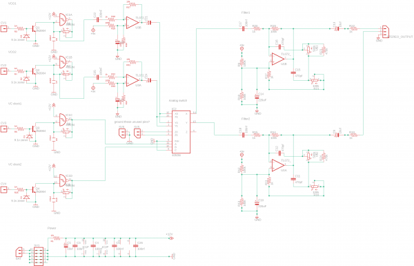
updated circuit.
The synth will be powered by 9v (battery) or maybe 12v adapter.
The Eurorack header might be skipped, depending on the layout
With my previous version, these voltages worked both. (without part changes)
The opamp amplification factor should be around 3x I think, so I will change the resistors to 3k + 10k
I've added the range resistors! Thanks, I forgot
The 100nF caps are already in place in the schematic, at the power section.
on the board they will be next to the IC's.
I've deleted the caps, except for c22 and 23. Is the offset no issue anymore? I will test this , it will be a prototype anyway. The c17 & 18 are now polarised 10uF, I guess you meant those.
| Description: |
|
| Filesize: |
126.37 KB |
| Viewed: |
352 Time(s) |
| This image has been reduced to fit the page. Click on it to enlarge. |
|
|
|
|
Back to top
|
|
|
Grumble
Joined: Nov 23, 2015
Posts: 1308
Location: Netherlands
Audio files: 30
|
| Posted: Tue Jan 28, 2020 8:42 am Post subject:
|
|
|
If the outputs of U3A and U3B aren't clipping, you can also remove C22 and 25, but then you have to be sure they fit nicely in the middle of the VCC and GND, a bit of fiddling with the values of R30 and 34 can help but I'm not sure about temperature stability of the output of IC1A and 1B, levels might shift...
If you want to keep C22 and 25: make'em bigger for low end frequencies.
Ah, the power caps, sorry I missed that!
Good goan 
_________________
my synth |
|
|
Back to top
|
|
|
fetideye
Joined: Jun 22, 2015
Posts: 27
Location: Netherlands
|
| Posted: Wed Jan 29, 2020 12:03 pm Post subject:
|
|
|
I've been adding features . like an on/off switch with led, volume pots
I might add switches for clock speed ranges and pwm .. feature creep
It is supposed to become a standalone pcb that can be mounted easily in a nice wooden enclosure. previously I wired everything.. no more
I'll post the updated schematic soon! |
|
|
Back to top
|
|
|
gabbagabi

Joined: Nov 29, 2008
Posts: 652
Location: Berlin by n8
Audio files: 23
|
| Posted: Wed Jan 29, 2020 4:45 pm Post subject:
|
|
|
hm,
first u try to get rid of the ofset from the oscillator, then u add an offest with the virtual ground in the Amplifier,
then u get rid of it again before the filter, and u add it again with the virtual ground in the filter?
may (or most probably as i see it) u only need a blocking cap on the filter output?
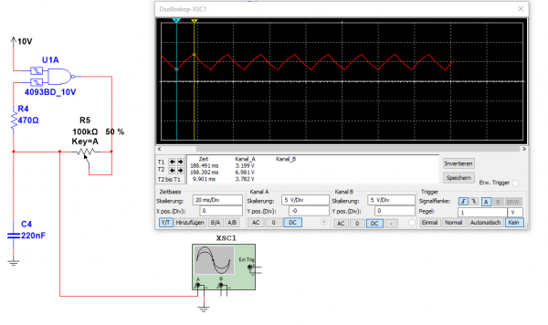
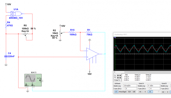
i did some simulations( with 10V supply )
- first the osc
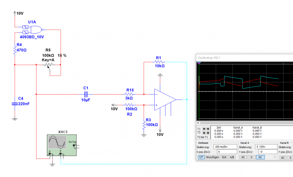
- then ive tried the osc and the amp, the result was that it seems to not work properly
- then a proposal if u need amplification and the possibility to push your signal up and down, the combination of 100k/75k gives u an amplifikation of 1.75, above that factor the signal startet to clip
The trimmer should be of small value in comparison with the 100k/R15, to keep the influence to the amp-factor low
This setup is also more like a real buffer, cos u are using the non-inverting op amp input which is famous for his high impendance and therefore it is not acting as a load for the previous circuit
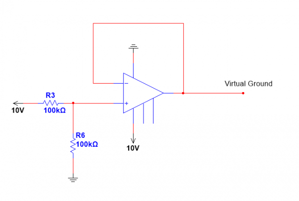
- second last a proposal how u could get virtual ground, instead of using repeatedly the Voltage dividers, i could also imagine that it could be an adantage to have such a virtual ground if u really need to drain something into ground
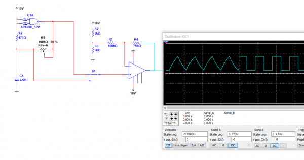
- last an other something on how to have a second waveform, and an other amp option
may u can tell something about the filter?
i really cant figure out what kind of filter u have there, but the combination 1k/100k would give u an amplifikation of -100 = clipping
cheers
gabi
| Description: |
|
| Filesize: |
32.8 KB |
| Viewed: |
294 Time(s) |
| This image has been reduced to fit the page. Click on it to enlarge. |
|
| Description: |
|
| Filesize: |
35.75 KB |
| Viewed: |
263 Time(s) |
| This image has been reduced to fit the page. Click on it to enlarge. |
|
| Description: |
|
| Filesize: |
36.52 KB |
| Viewed: |
300 Time(s) |
| This image has been reduced to fit the page. Click on it to enlarge. |
|
| Description: |
|
| Filesize: |
7.65 KB |
| Viewed: |
307 Time(s) |
| This image has been reduced to fit the page. Click on it to enlarge. |
|
| Description: |
|
| Filesize: |
28.52 KB |
| Viewed: |
277 Time(s) |
| This image has been reduced to fit the page. Click on it to enlarge. |
|
|
|
|
Back to top
|
|
|
Steveg

Joined: Apr 23, 2015
Posts: 184
Location: Perth, Australia
|
| Posted: Wed Jan 29, 2020 10:10 pm Post subject:
|
|
|
Hi Gabbagabi,
That looks like a Multiple Feedback low pass filter (MFB).
This is the Lunetta forum, amplification to clipping may not necessarily be seen as a fault.
Cheers! |
|
|
Back to top
|
|
|
Grumble
Joined: Nov 23, 2015
Posts: 1308
Location: Netherlands
Audio files: 30
|
| Posted: Wed Jan 29, 2020 11:15 pm Post subject:
|
|
|
| Steveg wrote: | | This is the Lunetta forum, amplification to clipping may not necessarily be seen as a fault. |
Ow, your’e right...
I was trying to get this circuit working without clipping...
_________________
my synth |
|
|
Back to top
|
|
|
fetideye
Joined: Jun 22, 2015
Posts: 27
Location: Netherlands
|
| Posted: Thu Jan 30, 2020 1:00 am Post subject:
|
|
|
Thanks for all replies!
This schematic is a bit hacked together, from several projects.
So I need to iron out some elements.
I think I will breadboard some elements of this circuit today. to see if it works or not. Simulations might also be helpful.
The idea is this:
the triangle waves (not distorted) should be from 0v to about 5 or 6v
Without amplification, the triangle is 2v with some offset.
What would be a good way to amplify this?
I tested a 4049 as amplifier. this works, but distorts the triangle on lower frequencies. (looks like a rounded square)
I'm testing the opamp setup now.
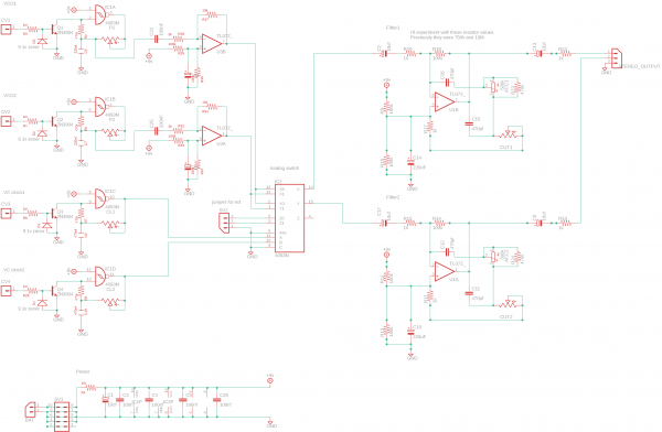
The lowpass filter comes from the WSG . originally it uses 750k + 10M resistors. see schematic
I put some random values in. not tested this yet - as an experiment. |
|
|
Back to top
|
|
|
fetideye
Joined: Jun 22, 2015
Posts: 27
Location: Netherlands
|
| Posted: Tue Feb 18, 2020 6:49 am Post subject:
|
|
|
I was experimenting with a better sounding triangle wave . I tried the 4006 stepped circuit that I found on this forum (cmos wave shaper) by Cynosure
which sounds wonderful. I might change it to the 4015 alternative.
I've added a sort of crossfader that blends between a stepped triangle and a smooth triangle waveform.
This OSC shape works also good on low frequencies. the shape stays intact. (unlike the 4093 or 10106 triangle circuit that I had)
I'll keep experimenting! |
|
|
Back to top
|
|
|
|

 Forum index » DIY Hardware and Software » Lunettas - circuits inspired by Stanley Lunetta